

The chapters listed here provide information about editing the components, which can be used for almost all objects regardless of their type:
There are different methods to open the "Edit Component Properties" window:
In the left part of the window, the properties of the component are displayed in up to eleven different tabs as shown below:
The previously existing tab "Extended Options" has been divided into the two tabs "Calculation" and "Experts".
Depending on the type of the component some tabs may be missing, because their contents would be empty.
The right part of the window displays the component as it is placed into the document. Its connectors are numbered. If you move the mouse over a connector, its description is displayed.
Inlets are marked by small white squares. Outlets are marked by small black squares.
If you activate the checkbox "Display options" below the component picture, the following options are displayed:
Show composition as default values:
For the components 1 or 33 or 132 for specifying a composition you enter the coefficients via the tab “Material fractions“. It is also possible to display all these coefficients in the main tab. This is less comfortable but particular helpful in connection with the Excel interface. This option is activated with the dropdown box “Display options“ below the component image by means of the entry “Show composition also as specification values“.
Enabling of extended property-pages:
In this dropdown box there is an option to hide and unhide unneeded tabs of the properties dialog under “Activate extended property tabs“. e.g. [Data-Bindings(SRx)]; [Calculation]; [Layout]; [Experts]; [ADAPT]
The checkbox "Load default values" below the component picture is used to overwrite the current values of all specification values with a value set from the default values database.
Above the component picture there is a drop down box where you can switch between the profiles. This allows you to get an overview of the specification or of the result values of different profiles without closing the property window.
In the lower part of the window there are three buttons.
The tab opened last is memorized, in the case of the component KernelScripting including the state of the script editor.
The undocked status of the KernelScripting editor can be activated in the general settings under User interface/Edit
Note:
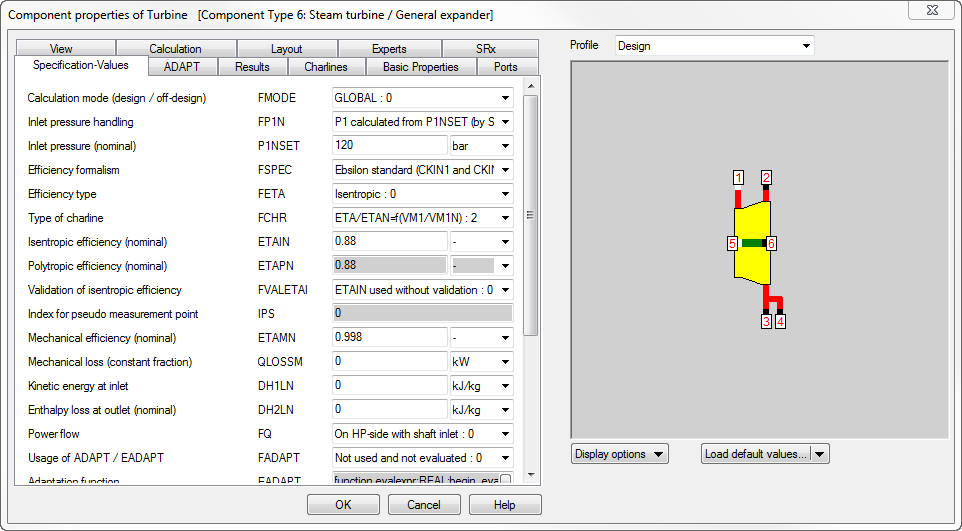
The tab "Specification Values" is used to display and change the specification values of the component selected. All specifications values (also called Spec-values) are listed.
The dialogue contains a navigation area (left), a data area (centre) and the preview area (right), the size of which can be changed by operating the split control elements located between these areas.
For some components (see image above) that have a particularly large number of specification values, there is a categorisation of the values into groups or subgroups. The groups or subgroups can be expanded or collapsed by clicking on the small black triangle to the left of the group name, so that the number of visible values can be determined, reduced or increased.
Each entry contains
The identifier is used to refer to a dedicated specification value in importing and exporting data. Furthermore, it can also help you in finding a special specification value when you are viewing a list of specification values.
The values listed belong to the active profile. Values printed in gray indicate, that this value is equal to the corresponding one within the parent profile of the activated Profile.
To change a value, move the mouse over the value field and click the left mouse button. For further information see Enter Specification Values.
To change the unit of a value, move the mouse over the unit field, click the left mouse button and select the unit from the list displayed. If you change the unit, the value displayed in the value field will be converted to the new unit and the value field will be updated with the calculated value.
If the input window is closed again, then the value is only in the selected unit, if you use the unit system used to view International Settings ("From component") activated.
Colour Coding on input descriptions and input fields:
The user entry descriptions printed in black are used as input data for Design and "Off-Design" simulations.
The user entry descriptions printed in blue are used as reference data for "Off Design" simulations only. They will be calculated in the design case.
The required input values are coloured black for the parent profile, regardless of global or local settings for design or off-design.
Black Input value in sub profile: different value from main profile value is used.
Greyed Out Entry field in sub profile: this value is equal to the corresponding one within the parent profile of the activated Profile.
Results of a Design simulation can be used as default values in sub profiles. To do this
Note though that using this option will not only serve as default values for the nominal values used for off-design calculation in the sub profiles, but it will also serve as default data for all input values in the sub profile cases.
Furthermore, note that using this option will not only serve as defaults for the values of off-design components in the sub profiles, but also the inputs of components set to global or local design in the sub profiles.
If there are more specification values than lines to display them a vertical scroll bar will be displayed at the right side of the list. Use this scroll bar to see and edit the last entries of the list.
In the property window of components, the basic quantities of the connected lines (P, T, H, M and Q respectively) are shown. However, the statement can also be hidden.
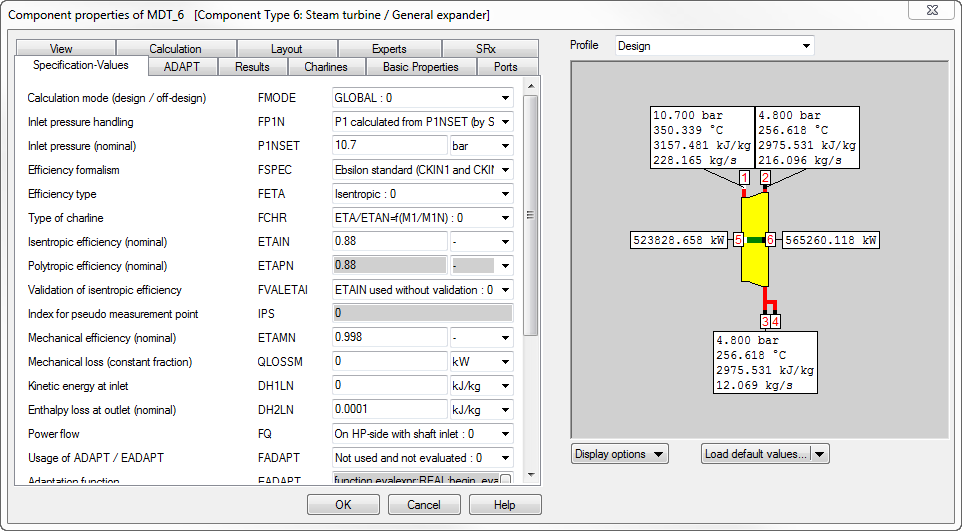
By right-clicking on a variable name, information can be copied to the clipboard with “Copy variable definition”. You can define via “Edit variable definition format” which information is to be copied. This information is used particularly by the new Excel interface / see chapter 4.2). Example: %EditComponents.html%s%EditComponents.html%i%EditComponents.html%c%EditComponents.html%u
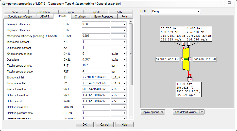
This tab "Results" is used to display the results (value and unit) of the component selected. All the results are listed.
Each entry includes
To change the unit of a value, move the mouse pointer over the unit field, click the left mouse button and select the unit from the list displayed. If you change the unit, the value displayed in the value field will be converted to the new unit and the value field will be updated with the calculated value.
If the output window is closed again, then the value will only remain in the selected unit get, if you have the unit system used to view International Settings (From component) activated.
If there are more results to display than the lines, then a vertical scroll-bar will be displayed at the right side of the list. Use this scroll-bar to view and edit the last entries of the list.
Press the "Help" button, if you want help to be displayed for the results.
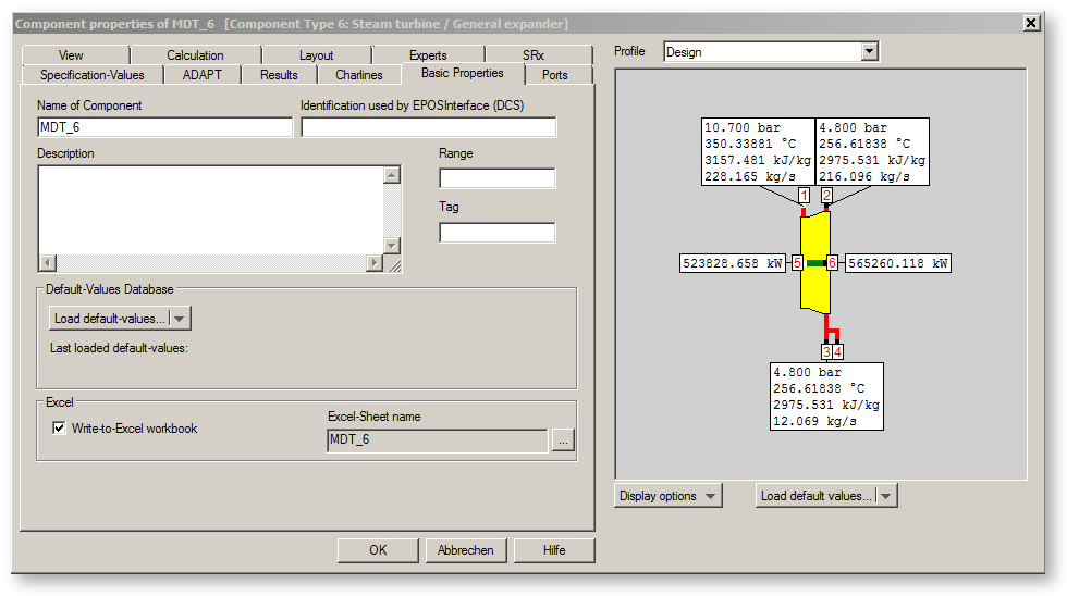
The field "Name of Component" is used to edit the name of the component. See objectnames for details of the rules for object names.
The field "Description" is used to enter an additional description for this component.
The field "Identification used by EPOSInterface (DCS)" helps in linking an object (normally a measurement value) with a control system. Enter the name here, under which the EPOSInterface receives the data from the control system.
The fields "Range" and "Tag" are freely available and can be used for classification and identification (e.g. reference to an EposArchive-Pot or to an R&I-Scheme).
The checkbox "Write-to-Excel-workbook" determines, whether the data of this component will be written in an Excel-workbook, if you export data to Excel with the help of the button "Write data of the active profile to Excel" on the tool bar.
The field "Excel-Sheet name" displays the name of the Excel sheet Standard Excel in the Standard Excel Workbook. By default, this is the same name as the component name.
The button "Load Standard Values" is used to overwrite the current values of all specification values with those from the standard values database (stdvalues.xml ).
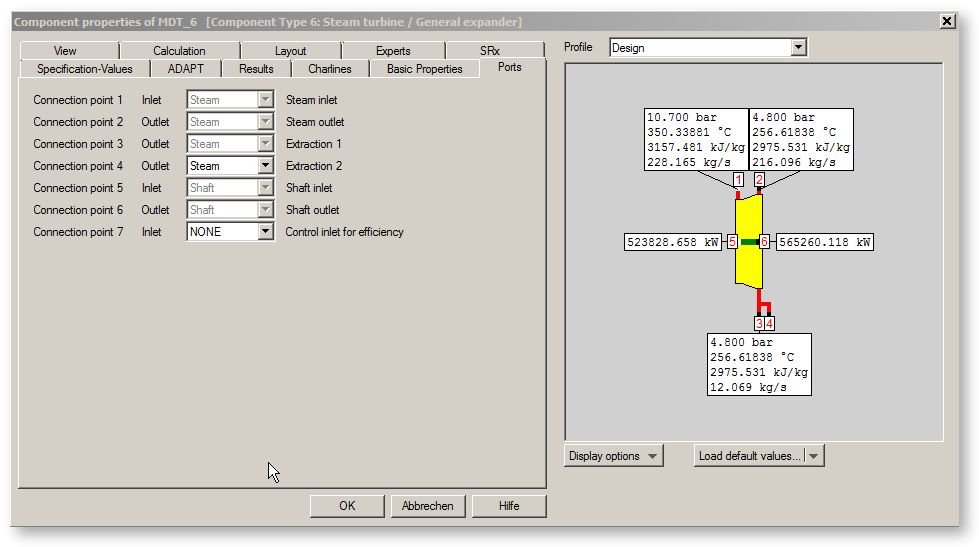
The "Ports" tab window shows the fluid types assigned to the component connectors.
There is an entry for each connector. It includes the connectors number and a combo box, which always displays the fluid type currently assigned.
You can change the fluid type of the connection points by clicking in the combo box fluids-type and selecting a type from the list displayed.
You cannot change the fluid type of connectors, if
For some components, it is possible to fade out an connection completely by specification of "None" as fluid.
Logic inlets for controlling component properties
The previous option for making component properties like efficiencies or heat transfer coefficients accessible from the outside (for control or validation) was to place the respective
value on an auxiliary line as an indexed measured value (specification value FIND). In the component, the same index then had to be entered as specification value IPS. In Release 11
it is possible to place these values also on a logic line that is directly connected to the component.
Example: Steam turbine (Component 6) - Connection point 7 - logic line, visible --> when selecting "logic"
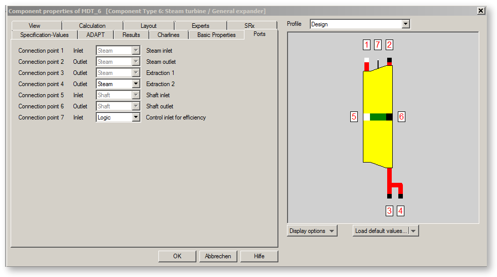
The advantage is that the allocation is graphically visible, and errors (e.g. when copying) are thus avoided. However, it has to be noted that the dimensions for these specifications
can no longer be chosen freely. Please refer to the following table (which is incomplete) to see which dimensions are expected. For the value of the connected line to be used, the respective flag has to
be set to “2 (given by dim on control inlet)“ as well.
|
Component no. |
Component |
Variation variable |
Flag |
Pin no. |
Dimension |
|
2 |
Throttle |
DP12RN |
FVALDP=2 |
3 |
Pressure |
|
6 |
Steam turbine |
ETAIN |
FVALETAI=2 |
7 |
Enthalpy |
|
7 |
Steam turbine condenser |
KAN |
FVALKA=2 |
6 |
Enthalpy |
|
8 |
Pump (fixed speed) |
ETAIN |
FVALETAI=2 |
4 |
Enthalpy |
|
10 |
Feed water preheater / heating condenser |
KAN |
FVALKA=2 |
6 |
Enthalpy |
|
11 |
Generator |
COSPHI |
FCOS=2 |
3 |
Mass flow |
|
11 |
Generator |
H2P |
FH2P=2 |
3 |
Pressure |
|
11 |
Generator |
GENF |
FGENF=2 |
3 |
Enthalpy |
|
13 |
Piping |
DP12RN |
FVALDP=2 |
3 |
Pressure |
|
18 |
Splitter with ratio specification |
M3M1 |
FVALM3M1=2 |
4 |
Mass flow |
|
19 |
Drain |
M3M1W |
FVALM3M1W=2 |
4 |
Mass flow |
|
23 |
Gas turbine (turbine only) |
ETAIN |
FVALETAI=2 |
5 |
Enthalpy |
|
24 |
Compressor/fan |
ETAIN |
FVALETAI=2 |
4 |
Enthalpy |
|
25 |
Air preheater |
KAN |
FVALKA=2 |
5 |
Enthalpy |
|
26 |
ECO/Evaporator/Superheater (characteristics) |
KAN |
FVALKA=2 |
5 |
Enthalpy |
|
27 |
After Cooler |
KAN |
FVALKA=2 |
5 |
Enthalpy |
|
61 |
ECO/Evaporator/Superheater (exponents) |
KAN |
FVALKA=2 |
5 |
Enthalpy |
|
94 |
Compressor with characteristics |
ETAN |
FVALETA=2 |
6 |
Enthalpy |
The activation of this logic line can be made conditional on the mode of calculation. This way, this feature can also be used for designs without having to switch manually all the time.
For this, the flag FVALxx features the settings
• FVALxx=4: use logic line in design mode, use specification value in off-design
• FVALxx=5: use specification value in design mode, use logic line in off-design
This option is available for Components 2, 6, 8, 13, 18, 19, 23, 24, and 94.
In the case of the heat exchangers these setting options are unnecessary as using the logic line for specifying KAN is only possible in off-design calculations anyway. In design mode, KAN is calculated by Ebsilon, of course.
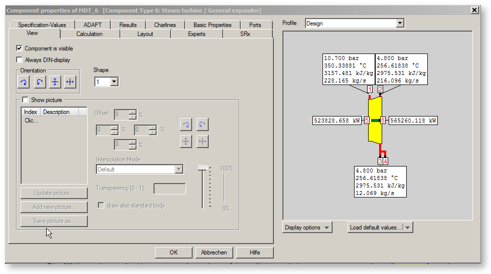
The sheet "View " is used to modify the look of the component.
The check box "Component is visible" determines, whether the component shall be visible or not. Note that the visibility is determined additionally by layer settings
The combo box "Shape" helps you to modify the shape of the selected component.
The checkbox "Always DIN-display" allows to activate the DIN display for single components. If this checkbox is activated, the component will be displayed in DIN-style even when the DIN display is not active for the whole cycle. The fluid pins are drawn according to the total settings anyway.
The four square buttons change the orientation of the shape (from top to bottom):
 Rotate 90° right
 Rotate 90° left
 Mirror horizontally
 Mirror vertically
If you change the shape or the orientation, the graphical representation on the right side of the window changes accordingly. Simultaneously all graphical representations in all active windows of the current document change too.
Existing connections to other components will not be deleted. Therefore, the pipelines connected will be stretched.
Usage of own graphics
By activation of the checkbox "Show picture", you may use your own pictures for the components as bitmaps. This is reasonable especially for macros and programmable components. The bitmaps have to be supplied in a file, but they are stored in the Ebsilon model afterwards.
The button "Load new picture" is used to load a picture from the disk. For this purpose, an "Open file" dialog appears to select the requested picture file. The new picture can replace the Ebsilon graphics completely or can be displayed additionally. This mode is activated by the checkbox "Draw also standard body" .
The picture size can be modified by specification of the offsets top, left, right and bottom.
The button "Save picture as..." opens the dialog "Save As".
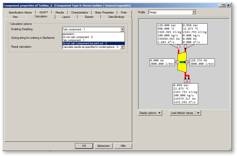
With the tab "Calculation" you can define how the component is handled by the computing core of Ebsilon®Professional.
There are options for the activation/deactivation of components and for manipulating their sequence in calculation.
With the setting (0): "Do not calc component" the component is used only as an image (passive graphics). This is e. g. useful when creating control room images.
The setting (1): "Calc component" (the default) enables the component to be used as an EBSILON-component and its data is transferred to and from the EBSILON®Professional-computing core.
With the setting (2): "Do not calc component but print out" the component is considered only as an image too and is not included in the calculation, but appears when printing reports (validation lists, Excel). This feature can be used for integrating the data in the EPOS-system.
It is not recommended to use the feature"Do not calc component" for disabling individual components (e.g. heat exchangers). Instead, specification value (like flag FFU) should be used for this. If a component is disabled in this way, it does not exist for the computing core any more, not even for the error analysis. The consequence is that the model topology displayed on the screen does not match with the topology available for the core.
In certain cases the convergence-behaviour may depend on the order the computing core processes the components, particularly if there are duplicate component names. The order is normally defined by chance based on the model’s structure. However, there is the possibility to exert influence on this order purposefully through sorting-strings that can be entered on the "Calculation" tab of the Component properties window. Sorting happens in accordance with the ASCII-table with a distinction between small and capital letters. All components get the sorting-string ”a” by default. If a component should be taken into the calculation later you should assign a string succeeding ”a” (in the ASCII-table) e.g. ”b” to it. Capital letters precede the small letters in the ASCII-table. So if a component should be dealt with earlier then you can assign to it a capital letter.
This feature is only important in special cases. In most models the order is not of any importance at all.
Result calculation
With the setting (0): Calculate all results as specified in model-options (Simulation --> Iteration)
With the setting (1): Calculate all results at each iteration step
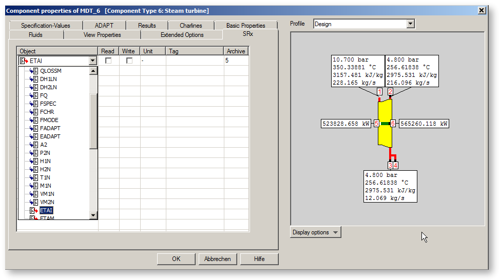
The sheet "SRx" is used to connect data in the model to a SRx server. In the table, you select specification and result values that should by imported from SRx or exported to SRx. Whether a value should be read or written (or both), is determined by the corresponding check boxes. In the column "Tag" you have to specify the name of the data point in the SRx server. At last, you have to specify which SRx archive is used for the data point.
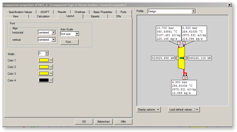
The tab "layout" allows to create of the component - font and colour (e.g. fill colour, border colour.).
There are two types of specification values:
In the image given below, the first line (FTYP) shows a flag. The second line (MEASM) is a numeric value.
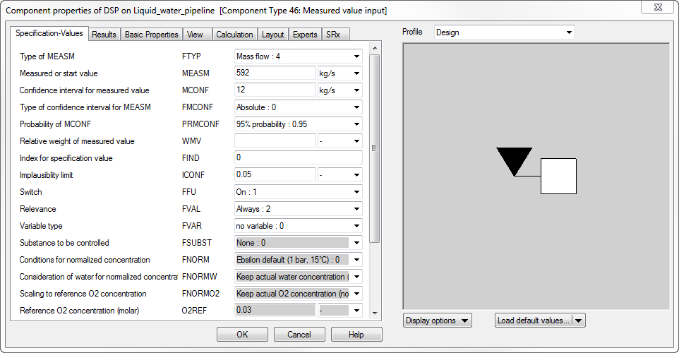
Numerical values are displayed as numbers, e.g. 123.4 within a text output field. This is followed by a combo box in which you can select the unit associated with this value. All these unit settings are saved in the model. However, they are only used effectively if the unit system ‘From component’ is selected in the general settings.
It is also possible to enter expressions in the numeric fields, which are written as per the EbsScript-Syntax.
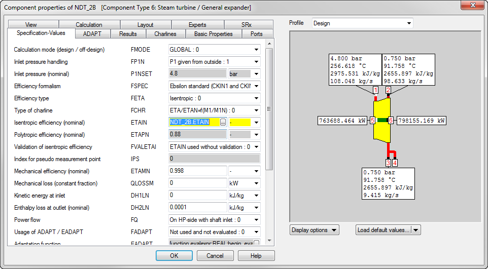
In the example given below, the expression "NDT_2A.ETAIN" is entered in the property window of the turbine NDT_2B as validation of isentropic efficiency. In this way, it is ensured that the turbines NDT_2A and NDT_2B always have the same nominal efficiency and, in case of a change, one only needs to change NDT_2A.
In these expressions, you may use the symbol "$" as a replacement for the component name. In the example above, the expression "0.02*$.MEASM" for the value MCONF assigns a value of 2% of MEASM to MCONF. The advantage of this syntax is that in case of renaming or copying, the reference is adjusted correctly to the new name.
These expressions are evaluated when you click on "OK" and upon the call of a calculation before the data is transferred to the computing core. Therefore, while the calculation is going on, this value is not changed any more. It is, thus, not recommended to process further a value calculated here. Even recursions are not possible: in case of a recursion the result is undefined (depending upon the random sequence of the evaluation).
Flags are displayed as text inside a combo box. The texts cannot be edited via the keyboard. You have to determine the value by selecting it from the entries of its combo box list. These entries are stored internally as integer numbers. You have to use the corresponding numbers only if you want to modify the flag by using EbsScript or by using Excel. Press the Help button to look up these numbers.
The value are changed within the active profile only. If a value is not defined in the active profile, but inherited from the parent profile, it is displayed in gray. If you edit such a value, it becomes black.
To change a value, move the mouse pointer over the value field and select it by clicking the left mouse button.
If you select a numerical value field, a cursor appears within the number.
Use your keyboard to edit the number. Additionally, you can click the right mouse button to get a sub-menu with the following edit commands and their keyboard shortcuts, which are also useful.
Use the TAB or die Shift-TAB key to move to the next or the previous value field.
If you select a flag field, its combo box list is opened and displayed. Use the mouse to select an entry from the list.
Use the TAB or die Shift-TAB key to move to the next or the previous value field.
Clearing a value is useful only for sub-profiles.
Clearing a value means specifying no value for a specification value within the active sub profile.
This is the default for all values of a newly created sub profile. Cleared values are displayed not in black, but instead in gray letters. The value displayed is that of the parent profile. A cleared value can be said to be transparent. You can look through it, looking at the value of the parent profile. This parent value is the valid value within the sub-profile. It is used in calculations. You may overwrite it at any time as described above.
To clear a numerical value, delete the number string displayed completely by
The value field will not remain empty. As soon as you select another value, it will show the corresponding value of the parent profile of the active profile. This value will be displayed in gray, indicating that a property has no dedicated value within this sub profile.
This is similar to using the clear function within EbsScript.
In certain cases, it is useful to assign the value "blank" to a specification value.
Allocating this value is possible only for numerical values. This is necessary for the components of the type 1, 33 and 46, especially when you do not wish to specify all its specification values, but instead only some of them.
Press the Ctrl-D key to empty a numeric value.
This is similar to using the set Empty function within an EbsScript.
There are several ways to rotate a component or to make its mirror-image.
For more information, see Rotate and Mirror.
There are several possibilities to change the graphical representation of a component back to its standard size.
The current orientation will not be changed.