EBSILON®Professional Online Documentation


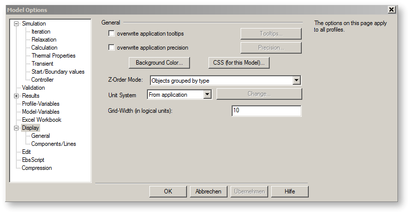
These options affect the display of the document.
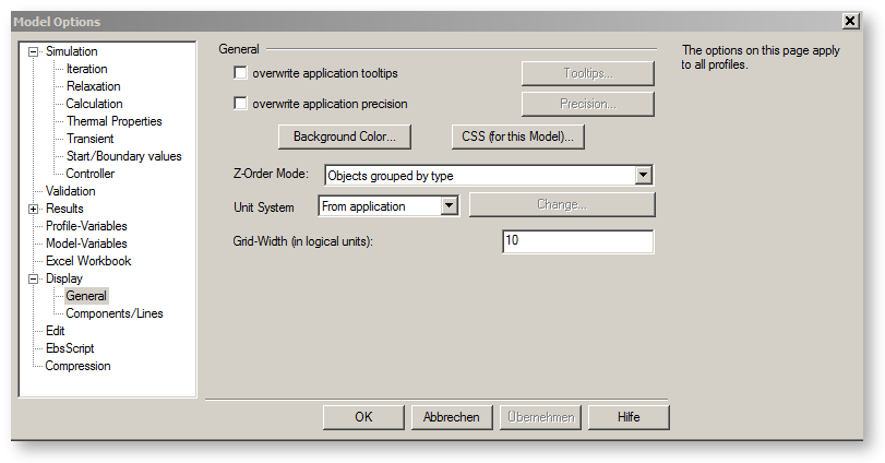
Overwrite application tooltips:
Using the “Tooltips” button you can choose which information is displayed in the tooltip window if you move the cursor over a component or row.
You can find more information about tooltips under Tooltips
Overwrite application precision:
The “Precision" button allows you to set the number of decimal digits that are displayed in the value crosses and tool tip displays.
Click the "Background Colour" button to change the background colour of your document. You can also modify the background colour via the option "View→Background Colour…" from the menu bar.
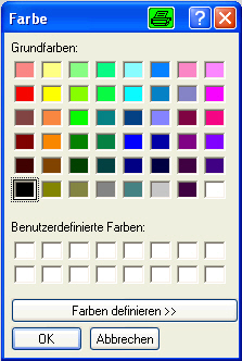
Note that the background colour is not printed.
CSS (for this Model)
Using the “CSS" button you can define CSS-commands for the whole application.
You can find more information about CSS and CSS-commands under CSS
Z-Order Mode
In the choice box “Z-Order Mode“, three modes for the Z-Order can be chosen.
1.) “Objects grouped by type“ – The specified levels remain in place. That means that components or lines can only be shifted forward or back within their level.
2.) “Free buttons and texts, rest grouped by type” – The specified levels remain in place. Only buttons and texts can be arbitrarily shifted between the levels.
3.) “Absolute free“ (even no fore- and background) – All components, lines, buttons, and text fields can arbitrarily be shifted forward or back.
Unit System
In the choice box “Unit system“, six modes for the Unit system can be chosen.
See: International settings (Unit system)
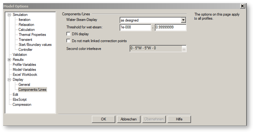
Under "Water/steam display" you can adjust the display of water and steam lines. By default, the display (blue for water lines, red for steam lines) follows the settings made in the model, regardless of what is the state in the line. This is the setting
as designed
In the case of the other displays, the colour of the line follows the state (steam mass fraction) in the line. There are the following options to choose from:
wet steam as steam
Only the colours blue and red are used, but the colour follows the steam mass fraction in the line. Wet-steam lines are displayed in red. The limit from which steam mass fraction onwards the red colour is to be used can be set under “Limit for wet steam” (in order to avoid that a water line with marginal evaporation is displayed in red)
interpolate wet-steam
The colour changes in a sliding way from blue (at X=0) via purple to red (at X=1)
intermediate wet-steam
All wet-steam lines are displayed in the same colour (purple). The limit from which steam mass fraction onwards the purple colour is to be used can be set under “Limit for wet steam”
If you check the box "DIN display", some pipelines and components (2, 4, 8, 13, 14, 17, 18, 19, 28, 37, 44, 49, 53, 54, 59, 60, 68) will be displayed using another style.
If you tick off the box "Do not mark linked connection points", connection points with pipelines connected will not be marked by the little input/output squares.
See also "check for superposing components / pipes" in Advanced - General
|
Linked connection points are not marked |
Linked connection points are marked |
|
|
|