EBSILON®Professional Online Documentation


The chapters listed here provide information about editing the components, which can be used for almost all objects regardless of their type:
A fluid type is assigned to each stream. The colour / thickness combination of any stream matches with its fluid type.
However, all these attributes can be changed by the user at any time.
|
Fluid type |
Colour |
Thickness |
Normal display |
DIN display |
|
Air |
yellow |
thick |
|
|
|
Steam |
red |
thick |
||
|
Oil |
petrol |
thin |
||
|
Liquid water |
blue |
thin |
||
|
Gas |
purple-red |
thin |
||
|
Flue gas |
brown |
thick |
||
|
Crude gas |
pink |
thick |
||
|
Coal / Ash |
brown |
thin |
||
|
Electric line |
pink |
thin |
||
|
Shaft |
green |
thick |
||
|
Scheduled value |
green |
thin |
||
|
Actual value |
yellow |
thin |
||
|
Logic |
black |
thin |
||
|
User-defined |
orange |
thin |
||
|
Salt water |
green |
thin |
||
|
2-phase-liquid fluid |
light blue |
thin |
||
|
2-phase-fluid gaseous |
light blue |
thick |
||
|
Universal fluid |
purple-red |
thin |
||
|
Binary mixture |
purple |
thick |
||
|
Oil / Melt |
grey |
thin |
||
|
Humid Air |
orange |
thin |
||
|
NASA |
dark blue |
thick |
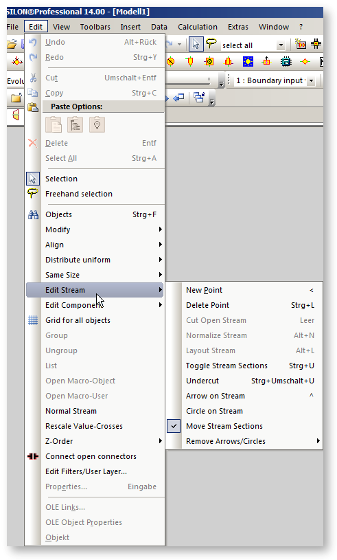
Streams may be divided into sections by creating separations points. At a separation point a stream may have a bending.
Additional separation points are created at positions of value crosses, components that are placed on the line and connection points of logical lines.
A display mode is assigned to each section: Visible, Invisible, Broken.
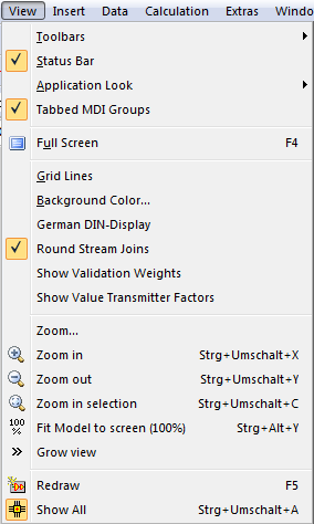
Streams or sections of streams, which have been set to ”Invisible” will generally not be visible in any document window, unless the menu bar entry ”ViewàShow All” is activated. For details concerning visibility of objects see the ”Layer” description.
Commands for editing lines (like e.g. normalizing a line) are pooled in the menu "Edit"à"Edit Stream".
You can insert a stream as described in Object Insertion.
Mostly it is easier to connect the two connection points of existing components. You have to do it in the following order:
If stream normalization is activated, the sections of the stream will be displayed horizontally and vertically.
If the cursor does not change when you click the second connection point, the input/output property of the connection point may not be correct. Only the connection points having different input/output properties can be connected (i.e. input/output or output/input, but not input/input or output/output).
There are the following simplifications for connecting lines to components:
When a line is deleted, the components (Components 33, 45, 46) and value crosses located on the line are removed. When inserting, they are inserted as well.
SHIFT-X and SHIFT-C respectively can be used to delete or copy only the line itself (without the connected objects).
Note:
On logic streams, mechanical shafts and electric streams, negative power values were accepted without error message from Release 10 up to and including Release 12.5, without a warning or error message being issued.
This way, users were not notified about possible errors in the modeling of internal consumptions. For this reason, 0 has been implemented as default lower limit for the output on shafts and electric lines. If this value is fallen below, it is limited to 0 and a warning is issued.
If desired, however, it is still possible to calculate with negative outputs. But to do so, a Component 147 with the desired lower limit has to be placed on the corresponding line.
The temperature on logic lines is only displayed on logic lines where the temperature is explicitly set by component 1, 33, 36, 46 or 144. If someone has written a script that has accessed the temperature of a logic line in other cases, this will return an error. The script must then access the enthalpy or the power instead.
There are several ways to open the ”Edit Stream Properties” window:
In the left part, the properties of the stream are displayed. They are displayed there in up to four different tabs:
The right part displays the stream as it is placed into the document.
If you activate the ”Show docking objects” checkbox below the stream picture, the components that are connected to the component are displayed. This is useful to determine whether a stream is really connected or is running behind the component.
Above this field with the stream picture, there is a drop down box where you can switch between the profiles. This allows to get an overview on the result values for different profiles without closing the property window.
There are three buttons present in the lower part of the window:
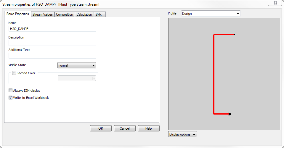
The ”Basic Properties” tab is used to display and change the following properties values of the stream selected.
The ”Name” field is used to edit the name of the stream. See Object names for details of the rules for object names.
The ”Description” field is used to enter an additional description for this stream.
The "Additional Text"field is used to give one more additional description. It is often used in online projects.
The ”Visible State” combo box determines the visual display of the stream selected. Possible values are:
Show All: All sections of the stream will be visible, even the ones set as invisible.
Hide All: No sections of the stream will be visible, unless the command ”ViewàShow All” is activated from the menu bar.
Normal: The command ”ViewàShow All” is activated from the menu bar: All sections are visible.
Menu command ”ViewàHide All” is deactivated: Only the sections marked as hidden are invisible.
See also Layers and Streams.
”Second Colour”: If the second colour is ”activated”, the stream is displayed in alternating colours. The combo box determines the second colour of all sections of the selected stream. The first colour of any stream is determined by its fluid type.
The checkbox ”Write to Excel-File” determines, whether data of this stream is written into the Excel workbook or not, when the button ”Write to workbook” is clicked in the tool bar.
Click the "Help" button, if you wish the help text to be displayed for the properties.
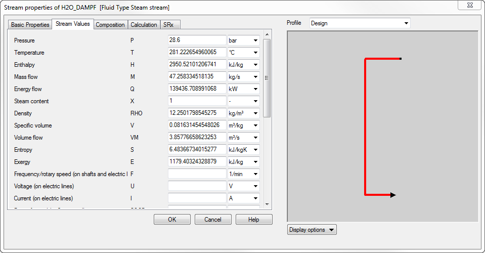
This ”Stream Values” tab is used to display the calculated results (value and unit) of the stream selected.
Each entry includes
To change the unit of a value, move the mouse pointer over the unit field, click the left mouse button and select the unit from the list displayed. If you change the unit, the value displayed in the value field is converted in the new unit and the value field will be updated with the calculated value.
If there are more results to display than the space available, then a vertical scroll-bar will be displayed to the right of the list. Use this scroll-bar to view and edit the last entries of the list.
Click on "Help", if you wish to view the help text for the displayed results.
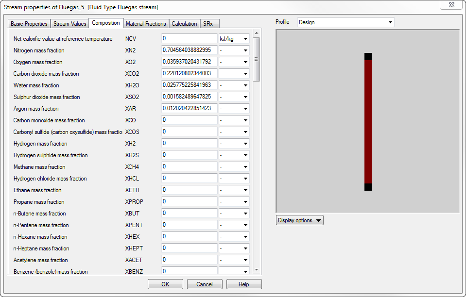
The left side of the window shows a list of the calculated material composition / other line parameters of the selected stream.
To change the unit of a value, move the mouse pointer over the unit field, click the left mouse button and select the unit from the list displayed. If you change the unit, the value displayed in the value field is converted in the new unit and the value field will be updated with the calculated value.
All values indicated on this sheet are mass ratios. To see the corresponding volume ratios, use the Material Table Tool.
Click on "Help" to view the help text for the selected data set.
On electric lines is in addition to the values
the value
provided.
It is possible to set for electric lines whether
applies.
The setting is made via the specification value NPHAS in the boundary value (Component 1) and start value (Component 33) respectively or in components with electric outlets.
In Ebsilon, this setting only affects the correlation of power output and current.
For direct current applies: active power Q = U * I
For one-phase alternating current applies: active power Q = U * I * cos (phi)
For three-phase alternating current applies: active power Q = U * I * cos (phi) * SQRT(3)
Thus when specifying the current, a power output increased by a factor of SQRT(3) is achieved for three-phase current.
NPHAS is transferred in the direction of the flow. When connecting lines with different NPHAS, the value of the main inlet is used.
Specification of voltage and frequency in the components
For the following components, the possibility has been created to specify the voltage and frequency as the default value in the component:
The flags FVOLT and FFREQ serve to set whether the specification is to be effected via the new specification values VOLT and FREQ respectively (0) or externally on the electric line, as before (-1).
For components that have an electric line as inlet
voltage and frequency are expected to be defined on the electric line.
See also: Types of streams (pipes)