
EBSILON®Professional Online Documentation


Definitions
All specification and result values of both fluids are named by using the port number as an index.
Colder fluid (to be warmed up), formerly primary side):
Warmer fluid (to be cooled down, formerly secondary side) :
Auxiliary condensate inlet (not in all heat exchangers): index 5 (port 5, connection point 5)
Example: T3: inlet temperature of the warmer fluid
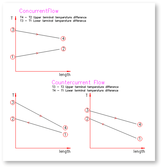
The heat exchanger can be operated according to the concurrent or according to the counter current flow principle.
In concurrent flow, both liquids flow in the same direction and in counter current flow in opposite direction through the heat exchanger (the cross flow where the directions are perpendicular to each other needs to be mentioned as well).
In the counter current flow principle, the maximum terminal temperature difference of the temperature diagram can appear both on the right and on the left side of the temperature diagram. This always depends on the water values of the fluids (m*cp, cp is the specific heat of the fluid).
Terminal temperature difference of the heat exchangers in concurrent and counter current flow
The terms “upper and lower terminal temperature difference” always refer to the cold flow (formerly: primary side).
The lower terminal temperature difference is always the temperature difference on the inlet side of the cold flow, the upper terminal temperature difference is always the temperature difference on the outlet side of the cold flow.
The "warm" sides of both flows are the sides with the higher amount of heat - i.e. the heat-emitting flow before release and the heat-absorbing flow after absorption. The direction of the heat flow in Ebsilon always runs from (3,4) to (1,2).
As in concurrent flow both flows enter on the same side, here the
lower terminal temperature difference T3-T1 is the "inlet terminal temperature difference" and the
upper terminal temperature difference T4-T2 is the "outlet terminal temperature difference" .
In counter current flow, however, the
lower terminal temperature difference T4-T1 is the temperature difference of the cold side of both flows and the
upper terminal temperature difference T3-T2 is the temperature difference of the hot side of both flows.
The following heat exchangers share many equations in common and are therefore very similar. The general equations are described further below, followed by a brief comparison of the different components key differences.
Steam Turbine Condenser (Component 7)
Feed Water Preheater / Heating Condenser (Component 10)
Air Preheater (Component 25)
Economizer / Evaporator / Super Heater (with Characteristic lines) (Component 26)
After-cooler (Component 27)
Desuperheater (Component 43)
High Temperature Heat Exchanger (Component 51)
Universal Heat Exchanger (Component 55)
DUPLEX Heat Exchanger (Component 62)
Heat Exchanger (Once Through Boiler) (Component 71)
Economizer / Evaporator / Super Heater (Finned Tubes) (Component 73)
Used Symbols:
Comp 7 Physics
M: Mass Flow
P: Pressure
H: Enthalpy
k: Overall Heat Transfer Coefficient
A: Heat Transfer Area
k*A: Heat Transfer Capability
LMTD: Mean Logarithmic Temperature Difference
QLOSS: Heat Losses to Environment
Number: Number of a port (connection point resp.) of an heat exchanger component
For all heat exchangers described in this section, the calculation is based on these six equations:
- Mass flow M1 = M2 (1)
M3 + M5 = M4 (2)
- Pressure P1 = P2 + DP12 (3)
P3 = P4 + DP34 (4a)
P5 = P3 (4b)
- Enthalpy (k*A)*LMTD = M2*H2 - M1*H1 (5)
(k*A)*LMTD = M3*H3 + M5*H5 - M4*H4 -QLOSS (6)
For equations (1) and (2), the mass flow must be specified
- M1 or M2, or
- M3, M5 or M4
The mass flow not specified is calculated. For the equations (3) and (4), the pressure must be specified
- P1 or P2 and
- P3 or P2
The pressure not specified is calculated.
The fundamental equations for enthalpy (5) and (6) can be used in two ways:
Default specification of the enthalpy
- H1 or H2, and
- H3 or H4
The enthalpy not specified is determined e.g. through the terminal temperature difference. Moreover, (k*A) is calculated.
Default specification of the enthalpy
- H1 or H2, and
- H3 or H4, respectively
The enthalpy not specified is defined by the (k*A)-entry. The terminal temperature differences are also calculated.
For design calculations, the effectiveness method is available for most heat exchangers. This option is selected - if available - via the flag FSPECD=0.
Exceptions:
For component 127, the effectiveness method can be specified with FCOOLING=3.
For component 151 the effectiveness method can be specified with FDES=1.
Note (see also VDU Heat Atlas C1 chapter 5.3):
Heat exchangers in which superheated steam is cooled, completely condensed and the condensate subcooled are to be considered as a coupled system of individual apparatuses. The same applies to the reverse case of evaporation. The three processes are calculated in separate apparatuses (or components in this case).
When using one ot this settings in a design calculation, Ebsilon calculates a theoretical (not realistic) maximum heat quantity QMAX that can be transferred in the heat exchanger. It is assumed that
In this case, Ebsilon (in extension of the NTU effectiveness method or the method from chapter C1 of the VDI heat atlas) takes into account:
The amount of heat actually transferred in this design calculation is then calculated to be QT = Qmax * EFF, where EFF is to be specified. From the QT calculated in this way, Ebsilon determines the associated value for k*A or KAN, DTM and the other nominal values. This KAN is then used as input in subsequent partial load calculations together with the characteristic curves or RADAPT or functions.
It is important to notice the definition of EFF in case of non-zero heat loss to the environment currently implemented in Ebsilon
EFF = (Q34 - QLOSS) / (Q34MAX - QLOSS)
QLOSS = DQLR*QN
If one wants to achieve in a design calculation the results of a calculation according to the NTU effectiveness method or the method used in the VDI Heat Atlas chapter C1 for the design of the heat exchangers, one must
For design calculations with other values of FSPECD and for all off-design calculations, the effectiveness is also calculatedas a result value. The result value REFF is implemented for this purpose. REFF is the ratio of the actually transferred heat to QMAX. For such design calculations, REFF is stored in the default value EFF when the reference values are adopted.
For components 61, 62 and 70, when "FFLOW=2 cross flow" is used, the calculation is applied following the NTU effectiveness method using equations from these publications:
1. VDI Wärmeatlas, Section Ca, 9. Auflage
2. H. A. Navarro and L. C. Cabezas-Gómez, “EFFECTIVENESS-NTU COMPUTATION WITH A MATHEMATICAL MODEL FOR CROSS-FLOW HEAT EXCHANGERS”, Brazilian Journal of Chemical Engineering, Vol. 24, No. 04, pp. 509 - 521,October - December, 2007
3. W.M. Kays and A.L. London, “Compact Heat Exchangers”, third edition, Krieger Publishing Company, Florida, 1998
In each case, it is necessary to specify:
If the flue gas and the water in the tube bundles move in the same direction, "FARR=1 Concurrent Flow" must be selected here. Otherwise, select "FARR=0 Countercurrent Flow". Same direction means here: Both streams in the boiler upwards or both in the boiler downwards.
The NTU effectiveness method is also used in the calculation of transient processes with component 7 (Condesnor).
For components 111 and 112: With FWETZONE=3 PWETZONE is interpreted as NTU ("number of transfer units"). This results in the Merkel number.
Also, in case of "FHYBRID=1 manual input" with "FHX=1 effectiveness" can be used to specify the effectiveness in PHX.
For components 112 and 127, NTU values are calculated and output as results.
The easiest method of deactivating a heat-exchanger without removing it from the model is to set the specification value FFU to "off". However, pressure losses continue to be considered.
The identification mode is always deactivated when the heat exchangers are switched off. This was not always the case in the past. In old models, where the outlet temperature is given from outside when the heat exchanger is switched off, this can lead to an overdetermination in the enthalpy.
Radiation losses can be defined by means of a loss factor DQLR / FDQLR .
The characteristic lines, which are available for most heat exchangers, can be corrected or replaced by an adaption polynomial or a Kernel expression.
If a phase transition occurs, the user must ensure that not only physically reasonable temperatures exist at the inlets and outlets. But also, the heat transfer must happen at the right temperature level. As the temperature remains constant during evaporation or condensation, it may happen that the amount of heat transfer corresponding to the specified inlet and outlet conditions is not possible ("pinch point violation", or local temperature crossover), even if it would be possible from the perspective of an overall balance.
In this case, Ebsilon reduces the heat transfer to a physically reasonable level. The input for variable PINPMIN (minimal pinch point) determines this "reasonable level". The reduction in heat transfer results in a decreased value of KA. In this case, a warning message is issued ("KA reduced to avoid pinch point violation"). You may adjust the off-design characteristics or exponents for KA in order to avoid this warning.
Heat exchangers for the water/steam cycle are
comp. 7
comp. 10
comp. 27
comp. 43
These heat exchangers are used in the water/steam cycle where steam or water is cooled down (i.e. is used on the secondary side).
Instead of water/steam, other 2-phase fluids can be used as working fluids, e.g. for Organic Rankine Cycles (ORC).
On the primary side (where the fluid is heated up), all fluids are possible.
Heat exchangers for the flue gas path are
comp. 25
comp. 26
comp. 27
comp. 61
These heat exchangers are used if water is heated up (i.e. on the primary side), or for fluids without a phase transitions.
comp. 25, 26, 27 are suitable for performance monitoring (easy adaptation of the off-design behaviour by characteristics),
comp. 61 is recommended for HRSGs.
This components simulates a water- or air-cooled condenser respectively. It is based on the same fundamental equations in addition to the assumption that the leaving condensate is saturated (h4=h'). This additional information makes the calculation of another quantity possible. Usually, for the design mode, these are the coolant flow rate M1, and for the off-design mode, the exhaust steam pressure P3, whereby M1 is presumed to be known.
This components simulates a feed water preheater or a heating condenser. It is based on the same fundamental equations in addition to the assumption that the leaving condensate is saturated (h4=h'). This additional information makes it possible to calculate the necessary mass flow of heating steam M3 in the design and off-design modes.
This component is based on the same fundamental equations. The only difference is that for the off-design mode (k*A) is calculated from the characteristic lines with different calculation specifications.
This component is based on the same fundamental equations. The only difference is that for the off-design mode (k*A) is calculated from the characteristic lines with different calculation specifications.
This component is based on the same fundamental equations. The only difference is that in the off-design mode (k*A) is calculated i.e. it is necessary to define the characteristic lines.
This component is based on the same fundamental equations. The only difference is that in the off-design mode (k*A) is calculated i.e. it is necessary to define the characteristic lines. Instead of the terminal temperature difference, the difference between the temperature of the desuperheater steam and the outlet saturation temperature is specified for the design case.
The calculation of the component is based on the basic equations. The difference is that radiation and heat conduction effects on (k * A) are taken into account. In addition, (k * A) can also be defined via a control entry.
The two characteristic curves (CALPM1, CALMP3) describe the convective heat transfer coefficients alpha12 and alpha34 as a function of the mass flows. For many other heat exchangers, the corresponding characteristic curves (CKAM1, CKAM3) describe the heat transfer capability k*A as a function of the mass flows.
This component is based on a similar physics and the similar user input values as component 51 but without consideration of radiation and heat conduction. All fluid combinations are possible.
This component was developed for the same purpose as component 26. The difference is that (k*A)-correction relations are used instead of characteristic lines.
This component was developed for the same purpose as component 61.. An important difference is that it is possible to simulate a duplex heat-exchanger.
Component 71 can be used to model a Benson boiler (once through boiler), which consists of an economizer, an evaporator and a super heater.
This component was developed for the same purpose as component 26 and 61. The difference is that fin efficiency is considered in component 73.
When using complex cycle arrangements for heat exchangers, it is often difficult to keep track of the settings of all terminal temperature differences successfully. As a result, a series of error messages often occurs, because an inoperable heat exchanger can cause errors in other heat exchangers.
To avoid this, enter (k*A) instead of terminal temperature differences and switch the component to FMODE="Local off-design". (k*A)-entries always lead to physically possible results. The desired result can be determined through iterative calculations with different (k*A) values.
Heat exchanger with NASA fluid and universal fluid: Since no automatic phase equilibrium calculation is performed in these fluids, the validity range of the material data for a specific composition is determined by the phase boundaries. In older versions of Ebsilon, the validity range was strictly adhered to and heat exchange across the phase boundary could not be modeled for these fluids. This behavior has been changed, i.e. temperatures outside the validity range can now also occur. In this case, however, a warning is issued and the correct equilibrium can be determined using a component 134 equilibrium reactor, for example.