EBSILON®Professional Online Documentation


|
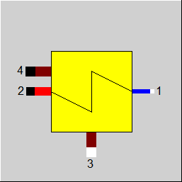
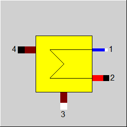
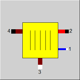
Line connections |
|
|
|
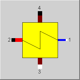
1 |
Primary inlet (cold stream, water / steam, inside tubes) |
|
|
2 |
Primary outlet (cold stream, water / steam, inside tubes) |
|
|
3 |
Secondary inlet (hot stream, outside tubes) |
|
|
4 |
Secondary outlet (hot stream, outside tubes) |
|
General User Input Values Physics Used Displays Example
Component 71 can be used to model a Benson boiler (once through boiler), which consists of an economizer, an evaporator and a super heater.
The boiler is modelled by
Component 71 defined as Economizer via FTYPHX = 1
Component 71 defined as Evaporator via FTYPHX = 2
Component 71 defined as super heater via FTYPHX = 3
The classification of the boiler in these three components is defined for the design case. That means that in design case only super heating occurs in the component marked as super heater, only evaporation occurs in the component marked as evaporator and only preheating (until saturation condition) is done in the economizer.
The component can be deactivated with the switch FFU = off. In that case, heat is no longer exchanged, but pressure losses are still taken into account.
In off-design case, the heat exchange surfaces for preheating, evaporation and super heating are different. Consequently, this means that in the economizer component (defined by design case) super heating or evaporation can occur. In the evaporator component (defined by design case) super heating or preheating can be done. And in the super heater (also defined by design case) preheating or evaporation can take place.
The following fluid combinations are possible:
|
primary inlet outlet |
secondary inlet/outlet |
|
Water Water, Steam Steam Steam 2-Phase liquid 2-Phase liquid, 2-Phase gaseous 2-Phase gaseous 2-Phase gaseous Saltwater Saltwater Binary mixture Binary mixture |
Air, Flue gas, Crude gas, Oil, Gas, User-defined, Thermo liquid Air, Flue gas, Crude gas, Oil, Gas, User-defined, Thermo liquid Air, Flue gas, Crude gas, Oil, Gas, User-defined, Thermo liquid Air, Flue gas, Crude gas, Oil, Gas, User-defined, Thermo liquid Air, Flue gas, Crude gas, Oil, Gas, User-defined, Thermo liquid Air, Flue gas, Crude gas, Oil, Gas, User-defined, Thermo liquid |
For more information on general notes applicable to most common heat exchangers, see Heat Exchanger General Notes
The (k*A)-value of the off-design calculation (Heat Transfer Capability) results from the (k*A)-value of the design calculation multiplied with a correction factor, which assumes a constant heat exchanger surface. The k-numbers are calculated from the individual heat transfer coefficients and the mass flow exponent.
Radiation losses can defined by means of a loss factor .
Pressure losses are taken into account by a constant friction factor ZETAN.
As compared to component 61, the important differences are:
In the design case, FSPECD= 6 [Economizer, given H2' (saturated water)] should be selected for the economizer. The terminal temperature difference DTN is not necessary. H2=H' is assumed.
In the design case, FSPECD= 7 [Evaporator, given H2=H2'' (saturated steam)] should be selected for the evaporator. The terminal temperature difference DTN=T4-T1 must be given. The mass flow M1=M2 is calculated.
Pinch point violations in the case of heat exchangers:
Up to release 10.0, a pinchpoint violation was only determined subsequently in partial load, i.e. KA was calculated for the respective load case and from this the transferred heat quantity and then it was checked whether this heat quantity can be transferred at all at the correct temperature level. Since in the case of evaporation or condensation the temperature remains constant despite heat input or heat removal, there are cases where heat transfer is not physically possible despite the overall balance being correct. In this case, an error message was issued in Ebsilon.
The calculation has now been changed in such a way that the transferred heat quantity is reduced as far as it is still physically possible, with the minimum pinch point
can be set in a default value PINPMIN. This results in a correspondingly reduced KA.
The user is informed of this by a warning message ("KA reduced to avoid pinchpoint violation") and can then adjust the part-load characteristic curve or the part-load exponent for KA accordingly so that the warning no longer occurs. The advantage, however, is that one gets a physically possible result in any case.
Furthermore, at the end of the calculation there is a check if there is a pinch point violation due to curved course of Q(T) (caused by significant changes of cp depending on the temperature). This can be verified by dividing the heat exchanger into individual sections.
This case can occur, for example, when on the hot side the cp at the inlet is significantly smaller than at the outlet (for example, steam that has a cp of about 2 kJ/kgK at high superheat, but more than 5 just above the boiling line). This means that this steam provides more heat at a lower temperature level than at a high one. At appropriately low degrees, this can be a limitation on the amount of heat transfer that is possible.
The QT diagrams take into account the non-linearity (curvature of the curves) in areas without phase change.
The flag FSPEC (deprecated) has been divided into two flags:
Note:
When loading a model that was created with Release 11 (or older), the corresponding values for FTYPHX, FSPECD, are determined from the value of the flag FSPEC, and FSPEC is set to “void” (-999). The model then calculates the same result values. If required, however, the flag FSPEC can still be used as well.
To remove ambiguity, the terms “primary side” and “secondary side” respectively have been replaced by “cold side” and “warm side” in the input screens. The cold side is the flow
from Pin 1 to Pin 2 that is heated. The warm side is the flow from Pin 3 to Pin 4 that gives off the heat.
Design in the Case of Concurrent Flow, see Heat Exchanger General Notes
In the heat exchanger (Components 71) it is possible to carry out a design via the upper and lower terminal temperature difference also in the case of concurrent flow (FFLOW=1).
If both inlet temperatures are specified, the upper terminal temperature difference can only be determined iteratively. Usually this is no problem. If convergence problems occur in more
complex models, another design mode will have to be used.
Flag FDQLR
It is possible, you can use the FDQLR flag to define how DQLR (factor for modeling heat losses) should be interpreted.
Specific heat capacity : CP12 / CP34
The mean specific heat capacity is now displayed as result value on the cold side (CP12) and on the hot side (CP34).
The mean specific heat capacity results from the quotient of the enthalpy difference and the temperature difference.
If no temperature difference is present (e.g. in the two-phase range or when the heat exchanger is shut off), however, it is not possible to calculate this quotient. In this case, the specific heat capacity at the respective temperature is used, provided that it is defined. Otherwise the result value will remain blank.
For more information on how this heat exchangers compares to other heat exchangers, see Heat Exchanger General Components
|
FTYPHX |
Type of heat exchanger Like in Parent Profile (Sub Profile option only) Expression = 1: Economizer |
|
FSPECD |
Calculation method in design-case Like in Parent Profile (Sub Profile option only) Expression = 1: Specification of the lower terminal temperature difference (=T4-T1) in the specification value DTN |
|
DTN |
Terminal temperature difference or temperature in the design case (nominal, see FSPEC) for FSPEC= 1, 7: lower terminal temperature difference (T4 - T1), see Heat Exchanger General Notes for FSPEC= 2 : upper terminal temperature difference (T3 - T2), see Heat Exchanger General Notes for FSPEC= 3 : T4 |
|
FDP12RN |
Pressure loss handling line 12 Like in Parent Profile (Sub Profile option only) Expression = 1: absolute (DP12N= DP12RN) |
|
DP12RN |
Pressure loss 12 (nominal) [absolute or relative to P1] |
|
FDP34RN |
Pressure loss handling line 34 Like in Parent Profile (Sub Profile option only) Expression = 1: absolute (DP34N= DP34RN) |
|
DP34RN |
Pressure loss 34 (nominal) [ absolute or relative to P3] |
|
FDQLR |
Heat loss handling Like in Parent Profile (Sub Profile option only) Expression =0: Constant (DQLR*QN in all load cases) |
|
DQLR |
Heat loss (QL relative to Q34) |
|
ALSUPN |
Heat transfer coefficient superheated, steam side (nominal) |
|
AL34N |
Heat transfer coefficient gas-side (nominal) |
|
KEVAECO |
Ratio k-Evaporator to k-Economizer |
|
KSUPECO |
Ratio k-superheated to k-Economizer |
|
FVOL |
Volume dependency of pressure loss Like in Parent Profile (Sub Profile option only) Expression =0: without =1: with |
|
EXSUP |
Mass flow exponent of ALSUP ALSUP = ALSUPN*(M1/M1N**EX12) |
|
EX34 |
Mass flow exponent of AL34 AL34 = AL34N*(M3/M3N**EX34)* (1 - (TM34N-TM34)*5E-4/°K) |
|
FFLOW |
Direction of flow Like in Parent Profile (Sub Profile option only) Expression =0: Counter Current flow =1: Concurrent flow |
|
FMODE |
Flag for calculation mode Design/Off-design Like in Parent Profile (Sub Profile option only) Expression =0: Global =1: local off-design (i.e. always off-design mode, even when a design calculation has been done globally) =2: special local off-design (Special case for compatibility with the earlier Ebsilon-versions, should not be used in new models, because the results =-1: local design |
|
FFU |
On-/Off switch Like in Parent Profile (Sub Profile option only) Expression =0: Heat-exchanger off =1: Heat-exchanger on |
|
FKAN |
KAN handling in off-design Like in Parent Profile (Sub Profile option only) Expression =0: Use A =1: Use KAN |
|
PINPMIN |
Minimum value for the pinch point (KA is reduced automatically if the pinch point would fall below this value) |
|
FSPEC (deprecated) |
Deprecated specification combi switch Like in Parent Profile (Sub Profile option only) Expression = -999: Unused (FSPECD and FIDENT used instead) Old values: =11: Economizer, user specifies DTN = lower terminal temperature difference =12: Economizer, user specifies DTN = upper terminal temperature difference =13: Economizer, user specifies DTN=T4 =14: Economizer, user specifies T3,T4 and T1 or T2 =15: Economizer, user specifies T1,T2 and T3 or T4 =16: Economizer, user specifies H2’ (saturated water) =19: Economizer, user specifies T2=T2sat(P2) =21: Evaporator, user specifies DTN = lower terminal temperature difference =22: Evaporator, user specifies DTN = upper terminal temperature difference =23: Evaporator, user specifies DTN=T4 =24: Evaporator, user specifies T3,T4 and T1 or T2 =25: Evaporator, user specifies T1,T2 and T3 or T4 =26: Evaporator, user specifies H2=H2’ (saturated water) =27: Evaporator, user specifies H2=H2’’ (saturated steam) and DTN=T4-T1 =28: Evaporator, user specifies M2 (saturated steam) =31: Superheated, user specifies DTN = lower terminal temperature difference =32: Superheated, user specifies DTN = upper terminal temperature difference =33: Superheated, user specifies DTN=T4 =34: Superheated, user specifies T3,T4 and T1 or T2 =35: Superheated, user specifies T1,T2 and T3 or T4 |
|
KAN |
K*A (nominal) - Design Heat Transfer Capability, see also FKAN |
|
QN |
Heat flow = Q34N |
|
M1N |
Primary mass flow (nominal) |
|
M3N |
Secondary mass flow (nominal) |
|
V1N |
Specific volume at point 1(nominal) |
|
V2N |
Specific volume at point 2 (nominal) |
|
V3N |
Specific volume at point 3 (nominal) |
|
TM34N |
Flue gas temperature (nominal) TM34N=(T3N+T4N)/2 |
|
P1N |
Pressure at point 1 (nominal) |
|
P3N |
Pressure at point 3 (nominal) |
|
ZETAN |
Friction factor at the water / steam side (nominal) ZETAN = DP12N/(0.5*A*M1N*M1N*(V1N+V2N) ) |
|
A |
Heat exchanger available, see also FKAN |
The parameters marked in blue are reference quantities for the off-design mode. The actual off-design values refer to these quantities in the equations used.
Generally, all inputs that are visible are required. But, often default values are provided.
For more information on colour of the input fields and their descriptions see Edit Component\Specification values
For more information on design vs. off-design and nominal values see General\Accept Nominal values
The equations of Component 61 are applicable.
 |
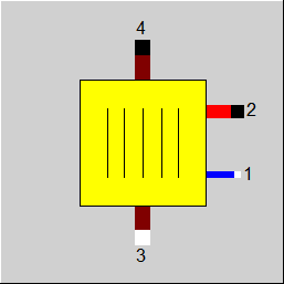
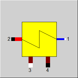
Display Option 1 |
 |
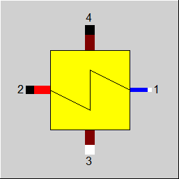
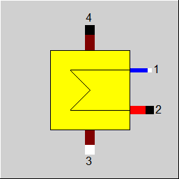
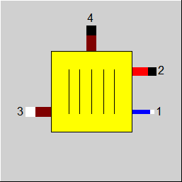
Display Option 2 |
 |
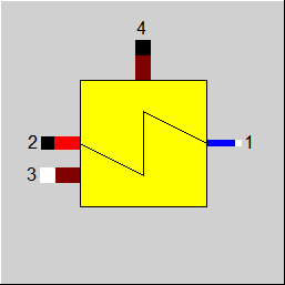
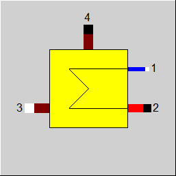
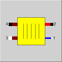
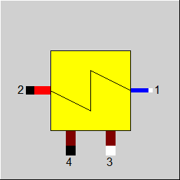
Display Option 3 |
 |
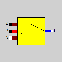
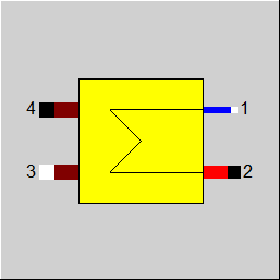
Display Option 4 |
 |
Display Option 5 |
 |
Display Option 6 |
 |
Display Option 7 |
 |
Display Option 8 |
 |
Display Option 9 |
 |
Display Option 10 |
 |
Display Option 11 |
 |
Display Option 12 |
 |
Display Option 13 |
 |
Display Option 14 |
Click here >> Component 71 Demo << to load an example.