
EBSILON®Professional Online Documentation


|
Line connections |
|
|
|
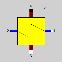
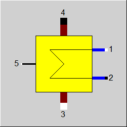
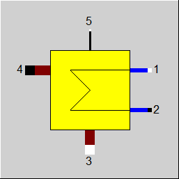
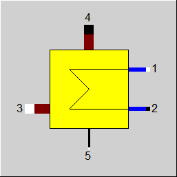
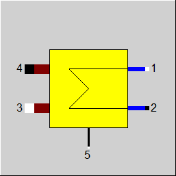
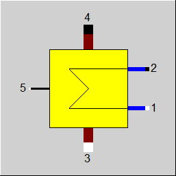
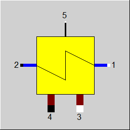
1 |
Primary inlet (colder stream, inside tubes) |
|
|
2 |
Primary outlet (colder stream, inside tubes) |
|
|
3 |
Secondary inlet (hotter stream, outside tubes) |
|
|
4 |
Secondary outlet (hotter stream, outside tubes) |
|
|
5 |
Control inlet for KAN - Design Heat Transfer Capability - (as H) |
|
General User Input Values Characteristic Lines Physics Used Displays Example
Module 61 is a multi-purpose module that can be inserted as economizer, evaporator or superheater. It differs from component 26 in the method of calculation of the (k*A)-values in the off-design mode. Component 26 takes a characteristic line as a basis, whereas component 61 uses the relationships of the individual sides heat transfer coefficients. The nominal values for the individual sides' heat transfer coefficient numbers and the exponents for the off-design scaling must be specified here.
The values available as default when inserting the component are suitable for water as the primary medium and flue gas as the secondary medium. An adjustment of the values is needed when using other fluids.
In the design case, the user must specify what type of heat exchanger the component will represent (as Economizer, Evaporator or Super Heater or also as general heat-exchanger). Moreover, the terminal temperature difference (upper and lower, (see Heat Exchanger General Notes )) or the flue gas inlet temperature in the design case must also be specified. Unless, the temperature specifications are used and instead of the terminal temperature different, the user specifies three of the four temperatures at the inlets and the outlets externally. In each case, the result of the design calculation is the nominal value for k*A, KAN.
Sizing the heat exchanger by using an effectiveness factor is also possible. It refers to the theoretically possible maximum heat exchange (for an infinitely large heat exchanger surface area). Thus an effectiveness of 0.8 means that 80 percent of the theoretically maximum possible heat is exchanged.
Pressure drop limitations in off-design (Extras --> Model Options--> Calculation -->Relative pressure-drop maximum) :
As the pressure drop rises quadratically with the mass flow, pressure drops that are significantly too high can quickly arise in the event of a transgression of the nominal mass flow. These will then cause phase transitions and convergence problems. For this reason, pressure drop limitations have been installed.
Constant pressure loss (FVOL=2):
For these components, it is possible to specify a constant pressure drop. This is especially helpful when the pressure drop is known for a certain part load point (from measurement, e.g.) or you want to use your own formula for the pressure drop.
In the off-design calculation mode, an off-design k*A is calculated from this KAN by using the physical laws. Optionally, an adaptation polynomial (as supplement or as replacement) can also be specified for the off-design scaling.
In partial load, a heat flow in the opposite direction is calculated when the temperature conditions at the connections are reversed.
Alternatively, there are also two identification modes (FIDENT = 2 and 4): T2-specification and T4-specification. In these modes, in the off-design case, one does not work with the KAN and the corresponding scaling laws, but instead calculates k*A in such a way that the result is the desired temperature. In the identification mode, it is not necessary to differentiate between an Economizer, Evaporator, Super Heater or general heat-exchanger.
Specification of the surface area for designing heat exchanger (specification value AN)
Usually, heat exchangers are designed in Ebsilon by specifying the terminal temperature differences or temperatures to be achieved. In an iterative process, the transferred amount of heat and the product of overall heat transfer coefficient k and surface area A (k*A) characteristic for the heat exchanger, the heat transfer capability, are calculated from this. Its nominal value KAN then serves to calculate the temperatures in off-design calculations. It is not necessary to know the individual values k and A here.
In the case of the components ECO/Evaporator/Superheater (exponents, Component 61), Duplex heat exchanger (Component 62), and Evaporator with steam drum (Component 70), however, the off-design behaviour is defined by exponents of convective heat transfer coefficients AL12 and AL34. As k can be calculated from it, the heat exchanger surface area A is available as well.
This has been used to implement a design calculation via the specification of the surface area. It is, however, essential to correctly specify the nominal values for the convective heat transfer coefficients AL12N and AL34N, which had only an effect on the partial load behaviour before to implementation of AN (area).
The specified surface area AN is only used for the design calculation to determine KAN from it. In the off-design calculation KAN is then used for the calculation.
Flag FAA to determine the heat transfer coefficients
The heat transfer coefficient is always calculated from the two heat transfer coefficients AL12N and AL34N for the cold and hot side respectively, which have to be specified by the user. At FSPECD=0 to 5, an inaccuracy in the specification of AL12N and AL34N has no effect on the heat exchange in the design case as it only depends on the product k*A. To determine the heat exchanger surface area AN from k*A, however, and also for the off-design behavior, a precise knowledge of k is required, and at FSPECD=9 also in the design case.
FAA = 0 determines AL12N and AL34N and also the corresponding off-design exponents EX12 and EX34 on the basis of the fluids connected to the component:
This mode is the default setting for newly inserted heat exchangers.
FAA = 1 uses the specification values AL12N, AL34N, EX12, and EX34. This corresponds to the previous behavior.
Therefore heat exchangers created with an older version of Ebsilon are automatically set to this mode so that the results remain unchanged.
FAA = 2 can be used for calculating the heat transfer coefficient AL12N, provided that the surface area AN is known. However, this option is only available at FSPECD = 0 to 5 as another specification value is required in addition to the surface area. As far as possible, AL34N and both exponents are taken from the database.
FAA = 3 can be used for calculating the heat transfer coefficient AL34N, provided that the surface area AN is known. However, this option is only available at FSPECD = 0 to 5 as another specification value is required in addition to the surface area. As far as possible, AL12N and both exponents are taken from the database.
FAA = 4 can be used for calculating the heat transfer coefficient AL12N, provided that the surface area AN is known. However, this option is only available at FSPECD = 0 to 5 as another specification value is required in addition to the surface area. Unlike at FAA = 2, at FAA = 4 the specification values are used for AL34N and the two exponents.
FAA = 5 can be used for calculating the heat transfer coefficient AL34N, provided that the surface area AN is known. However, this option is only available at FSPECD = 0 to 5 as another specification value is required in addition to the surface area. Unlike at FAA = 3, at FAA = 5 the specification values are used for AL12N and the two exponents.
The component can be deactivated with the switch FFU. In that case, heat is no longer exchanged, but pressure losses are still taken into account.
Radiation losses DQLR can defined by means of a loss factor.
A design calculation is possible only in the counter current flow. In the concurrent flow, a calculation can be done only in the local off-design mode.
As the part load behaviour of this component is not determined by a characteristic but by the specified exponents, the transition from identification mode to what-if mode cannot be achieved by a simple multiplication with a factor KA/KACL. Therefore, there is a result value KAN0. This is the hypothetical value of KAN that would yield the current value of KA (as it was determined by the identification).
For the off-design behaviour of k*A, an EbsScript function in the specification field EADAPT can be used as an alternative to the adaptation polynomial ADAPT.
Logic inlet (Connection point 5) for controlling component properties
(see : Edit objects --> Ports)
To make component properties like efficiencies or heat transfer coefficients (variation quantity) accessible from the outside (for control or reconciliation) it is possible to place the respective value on an auxiliary line as an indexed measured value (specification value FIND). In the component, the same index must then be entered as specification value IPS.
It is also possible to place this value on a logic line that is directly connected to the component (please see FVALKA=2, Variation variable: KAN, Dimension: Enthalpy).
The advantage is that the allocation is now graphically visible, and errors (e.g. when copying) are thus avoided.
Note to flag FCALC :
If you use this component for a primary fluid different from water/steam, it is required to modify the values for the heat transfer coefficients and the mass flow exponents as the default
values are suitable to water/steam only. In former EBSILON®Professional-versions (up to release 5.0), there was an automatic interchange of the coefficients of the cold side and the
hot side.
From release 6.0 on, this interchange can be activated or deactivated by a flag FCALC. With FCALC=1, the component is calculated like in former Ebsilon releases (with an exchange of coefficients if there is no water or steam on the primary side). With FCALC=2 the component uses the coefficients just as they are specified.
The default value is FCALC = 1 when you open an old model file (so that the result will be the same as before) and FCALC = 2 when you insert a new component 61.
Pinch point violations in the case of heat exchangers
Up to release 10.0, a pinchpoint violation was only determined subsequently in partial load, i.e. KA was calculated for the respective load case and from this the transferred heat quantity and then it was checked whether this heat quantity can be transferred at all at the correct temperature level. Since in the case of evaporation or condensation the temperature remains constant despite heat input or heat removal, there are cases where heat transfer is not physically possible despite the overall balance being correct. In this case, an error message was issued in Ebsilon.
The calculation has now been changed in such a way that the transferred heat quantity is reduced as far as it is still physically possible, with the minimum pinch point
can be set in a default value PINPMIN. This results in a correspondingly reduced KA.
The user is informed of this by a warning message ("KA reduced to avoid pinchpoint violation") and can then adjust the part-load characteristic curve or the part-load exponent for KA accordingly so that the warning no longer occurs. The advantage, however, is that one gets a physically possible result in any case.
Furthermore, at the end of the calculation there is a check if there is a pinch point violation due to curved course of Q(T) (caused by significant changes of cp depending on the temperature). This can be verified by dividing the heat exchanger into individual sections.
This case can occur, for example, when on the hot side the cp at the inlet is significantly smaller than at the outlet (for example, steam that has a cp of about 2 kJ/kgK at high superheat, but more than 5 just above the boiling line). This means that this steam provides more heat at a lower temperature level than at a high one. At appropriately low degrees, this can be a limitation on the amount of heat transfer that is possible.
The QT diagrams take into account the non-linearity (curvature of the curves) in areas without phase change.
The flag FSPEC (deprecated) has been divided into three flags:
Note:
When loading a model that was created with Release 11 (or older), the corresponding values for FTYPHX, FSPECD, and FIDENT are determined from the value of the flag FSPEC, and FSPEC is set to “void” (-999). The model then calculates the same result values. If required, however, the flag FSPEC can still be used as well. This is necessary so that the existing EbsScripts in which a switchover of FSPEC into an identification mode is carried out will continue working. If FSPEC is not “empty” (-999) but has a value of -4 or -5 (the old values for the identification modes), the new flag FIDENT will be ignored, and the component will behave according to the setting of FSPEC (this is indicated in a comment).
To remove ambiguity, the terms “primary side” and “secondary side” respectively have been replaced by “cold side” and “warm side” in the input screens. The cold side (previously “primary”) is the flow from Pin 1 to Pin 2 that is heated. The warm side (previously “secondary”) is the flow from Pin 3 to Pin 4 that gives off the heat.
Design in the Case of Concurrent Flow see Heat Exchanger General Notes
In the heat exchanger (Components 61) it is possible to carry out a design via the upper and lower terminal temperature difference also in the case of concurrent flow (FFLOW=1).
If both inlet temperatures are specified, the upper terminal temperature difference can only be determined iteratively. Usually this is no problem. If convergence problems occur in more
complex models, another design mode will have to be used.
Note for heat exchanger type evaporator:
For an evaporator, the outlet temperature is defined by the pressure. Thus in this case one degree of freedom less is available. Therefore specifying the upper terminal temperature difference (in counter current flow) was not possible for the evaporator.
It is possible also in the case of an evaporator to specify the upper (in counter current flow) and lower (in concurrent flow) terminal temperature difference respectively for the design. In this case the component then calculates the inlet temperature of the warm fluid. To use this mode, however, FTYPHX has to be set to “Evaporation without super heating” (5)
(implemented in Component 61). The reason is that with the setting “Evaporator” (2) superheated steam is accepted at the outlet as well, and therefore the outlet temperature is unknown.
Effectiveness Method
See Heat Exchangers General Information Effectiveness Method
The effectiveness method is also available for the design. Analogous to other heat exchangers, this option is selected via the switch FSPECD=0 . The effectiveness is also calculated in the heat exchanger calculation for other design methods (but not in the identification mode). For this purpose, a result value REFF was introduced.
REFF is the ratio of the heat actually transferred to the theoretical maximum that could be achieved with an infinitely large exchange surface. REFF depends on the size of the heat exchanger.
In the design case, the calculated effectiveness is also stored in the default value EFF when the reference values are adopted.
Flag FDQLR
It is possible, you can use the FDQLR flag to define how DQLR (factor for modeling heat losses) should be interpreted.
Specific heat capacity : CP12 / CP34
The mean specific heat capacity is now displayed as result value on the cold side (CP12) and on the hot side (CP34).
The mean specific heat capacity results from the quotient of the enthalpy difference and the temperature difference.
If no temperature difference is present (e.g. in the two-phase range or when the heat exchanger is shut off), however, it is not possible to calculate this quotient. In this case, the specific heat capacity at the respective temperature is used, provided that it is defined. Otherwise the result value will remain blank.
Performance factor RPFHX
The quotient from the current value for k*A (result value KA) and the k*A expected in the respective load point due to the component physics and characteristic lines respectively (result value KACL) serves to assess the condition of a heat exchanger.
The quotient KA / KACL is displayed as a result value RPFHX.
Component 61 enables the modeling of transient processes (e.g. load changes). This calculation type is activated with the FINST switch.
The heat exchange surface (AN) is available in component 61. For the transient calculation, it is necessary to specify the parameters for converting the heat exchange surface into the mass of the pipes. These parameters can
The user is expected to enter the density RHOP and the specific heat capacity CP for the material details of the tubes. Since the component 61 calculates the heat transfer in a simplified way, only depending on the alpha numbers of the fluids 1-2 and 3-4, the dependence on the thermal conductivity of the material is neglected in the transient calculation.
The heat exchange between the medium and the pipe wall or temperature development in the walls over time is calculated using the combined analytical and numerical model (as in component 126). The number of elements in the flow direction (NFLOW) is specified for the numerical discretization. This has the consequence that the calculation result depends on the value of NFLOW.
Attention! The values AN, AL12N, AL34N, EX12, EX34 are used in the transient calculation. A correct design calculation (design mode) ensures consistency between these values and the value KAN. This consistency is very important and can be destroyed by changing just one of the specified default values.
For more information on general notes applicable to most common heat exchangers, see Heat Exchanger General Notes
|
FTYPHX |
Type of heat exchanger = 0: General heat exchanger |
|
FSPECD |
Calculation method in design-case = 0: Specification of the effectiveness (ratio of transferred heat to the theoretical maximum at infinite transfer surface) in the specification value EFF |
|
FIDENT |
Activation of a component identification mode (only in off-design) (FIDENT serves to activate a component identification mode, i.e. the respective condition of the component is determined on the basis of temperature specifications) = 0: No identification mode In the design case, variant FIDENT=2 is identical with FSPECD=5 and FIDENT=4 with FSPECD=4. In order to prevent contradictory specifications, the flag FIDENT is therefore only used in off-design for this component. Please note: the peculiarity for these components is that in the design case identification (namely the calculation of KAN from temperature specifications) takes place by default. |
|
DTN |
Terminal temperature difference (nominal,s. FSPEC) |
|
EFF |
Effectiveness |
|
FDP12RN |
Flag for the type of definition pressure drop of the cold side =1: absolute (DP12N=DP12RN) =2: relative (DP12N=P1N*DP12RN) = -1: P2 given from outside |
|
DP12RN |
Pressure drop 12 (nominal) [absolute or relative to P1] |
|
FDP34RN |
Flag for the type of definition pressure drop of the hot side =1: Calculated by (DP34N=DP34RN) absolute =2: Calculated by (DP34N=P3N*DP34RN) relative = -1: P4 given from outside |
|
DP34RN |
Pressure drop 34 (nominal) [absolute or relative to P3] |
| FDPNUM |
Pressure loss handling in the numerical solution =0: Using the average fluid pressure between inlet and outlet |
| FVOL |
Flag for considering the dependency of pressure loss on volume =0: only depending on mass flow DP/DPN = (M/MN)**2 =1: depending on mass and volume flow DP/DPN = V/VN*(M/MN)**2 =2: constant pressure drop (no load dependency) |
|
FDQLR |
Heat loss handling =0: Constant (DQLR*QN in all load cases) |
|
DQLR |
Heat loss (relative) |
|
FCALC |
Part-load calculation type (see "General") =1: Old mode (for compatibility) =2: New mode |
|
AL12N |
Cold side heat transfer coefficient (nominal) The following values are recommended as the first assumption: AL12N_Water = 6000 W/(m²K) AL12N_Steam = 500 W/(m²K) |
|
AL34N |
Hot side heat transfer coefficient (nominal) The following values are recommended as the first assumption: AL34N_Gas = 50 W/(m²K) |
| AL34RN | Hot side radiation transfer coefficient (nominal) |
| DAL34DT |
Additional off-design temperature gradient for AL34 - see Chapter Heat Transfer The temperature dependency of AL34 can thus be influenced - default value up to release 16: 0.0005 As the temperature dependency is calculated using the radiation formula when AL34RN is specified, it makes sense to set DAL34DT=0 in this case. Otherwise, both corrections are carried out |
|
EX12 |
Mass flow exponent of AL12 AL12 = AL12N*(M1/M1N**EX12) |
|
EX34 |
Mass flow exponent of AL34 AL34 = AL34N*(M3/M3N**EX34)* (1 - (TM34N-TM34)*5E-4 /K) (K= degrees Kelvin) |
|
AN |
Heat transfer area (nominal) |
|
FMODE |
Flag for calculation mode Design/Off-design =0: Global =1: local off-design (i.e. always off-design mode, even when a design calculation has been done globally) =2: special local off-design (Special case for compatibility with the earlier Ebsilon-versions, should not be used in new models, because the results of the real off-design calculations are not always consistent) = -1: local design |
|
FFLOW |
Direction of flow see Heat Exchanger General Notes =0: Counter Current flow =1: Concurrent flow =2: Cross flow |
|
NROW |
Number of rows (for cross flow) |
|
NPASS |
Number of passes (for cross flow) |
|
FARR |
Arrangement of passes (for cross flow) =0: Counter Current flow =1: Concurrent flow =2: Cross Flow |
|
FADAPT |
Flag for using the adaptation polynomial ADAPT / adaptation function EADAPT =0: Not used and not evaluated =1: Correction for k*A [KA = KAN * K/KN * polynomial] =2: Calculation of k*A [KA = KAN * polynomial] =1000: Not used but ADAPT evaluated as RADAPT (Reduction of the computing time) =-1: Correction for k*A [KA = KAN * K/KN* adaptation function] =-2: Calculation of k*A [KA = KAN * adaptation function ] =-1000: Not used but EADAPT evaluated as RADAPT (Reduction of the computing time) |
|
EADAPT |
Input of Adaptation-Function |
|
FFU |
On-/Off switch =0: Heat-exchanger off (no heat transfer, but pressure losses) =1: Heat-exchanger on (active) |
|
FVALKA |
Validation of k*A =0: KAN used without validation =1: ISP used instead of KAN (can be validated) =2: KAN given by enthalpy on control inlet 5 |
|
IPS |
Index on the pseudo measurement point |
|
PINPMIN |
Minimum value for the pinch point (KA is reduced automatically if the pinch point would fall below this value) |
|
TOLXECO |
Tolerance for evaporation in an economizer. If the steam content X at the economizer outlet is > TOLXECO, a warning message is issued. If it is > 2*TOLXECO, an error message is issued. |
|
FSPEC (deprecated) |
Flag for operation type and temperature definitions (except for the last two modes, FSPEC is only used in the design case) = -999: unused (FSPECD and FIDENT used instead) old values: =40: General heat-exchanger, effectiveness method =41: General heat-exchanger, DTN= lower terminal temperature difference given =42: General heat-exchanger, DTN= upper terminal temperature difference given =43: General heat-exchanger, DTN= T4 given =44: General heat-exchanger, (T3,T4) and (T1 or T2) outside of this component given =45: General heat-exchanger, (T1,T2) and (T3 or T4) outside of this component given =49: General heat-exchanger, AN=area given =10: Economizer, effectiveness method =11: Economizer, DTN= lower terminal temperature difference given =12: Economizer, DTN= upper terminal temperature difference given =13: Economizer, DTN= T4 given =14: Economizer, (T3,T4) and (T1 or T2) outside of this component given =15: Economizer, (T1,T2) and (T3 or T4) outside of this component given =19: Economizer; AN=area given =20: Evaporator, effectiveness method =21: Evaporator, DTN= lower terminal temperature difference given =22: Evaporator, DTN= upper terminal temperature difference given =23: Evaporator, DTN= T4 given =24: Evaporator, (T3,T4) and (T1 or T2) outside of this component given =25: Evaporator, (T1,T2) and (T3 or T4) outside of this component given =29: Evaporator, AN=area given =30: Super Heater, effectiveness method =31: Super Heater, DTN= lower terminal temperature difference given =32: Super Heater, DTN= upper terminal temperature difference given =33: Super Heater, DTN= T4 given =34: Super Heater, (T3,T4) and (T1 or T2) outside of this component given =35: Super Heater, (T1,T2) and (T3 or T4) outside of this component given =39: Super Heater, AN=area given
=2: General heat-exchanger, DTN=upper terminal temperature difference given, off-design depending on EX12 only =3: General heat-exchanger, DTN=T4 given, off-design depending on EX12 only =4: General heat-exchanger, DTN=given T3, T4 and T1 or T2, off-design depending on EX12 only =5: General heat-exchanger, DTN=given T1, T2 and T3 or T4, off-design depending on EX12 only =-5: T2 given(also in off-design). Note: If this method is used in off-design, the mass and energy balances will be observed, but the heat exchanger will be resized. Use this method only when appropriate, such as for data reconciliation. This method could violate the second law of thermodynamics. =-4: T4 given(also in off-design). Note: If this method is used in off-design, the mass and energy balances will be observed, but the heat exchanger will be resized. Use this method only when appropriate, such as for data reconciliation. This method could violate the second law of thermodynamics. |
|
KAN |
Heat transfer coefficient * area (nominal) - Design Heat Transfer Capability |
|
QN |
Heat exchanger capacity (nominal) =Q34N |
|
M1N |
Cold side mass flow(nominal) |
|
M3N |
Hot side mass flow(nominal) |
|
V1N |
Specific volume at cold side inlet (nominal) |
|
V3N |
Specific volume at hot side inlet (nominal) |
|
P1N |
Pressure at cold side inlet (nominal) |
|
P3N |
Pressure at hot side inlet (nominal) |
|
TM34N |
Medium temperature of flue gas (nominal) TM34N=(T3N+T4N)/2 |
| T34N | Medium radiation temperature (geometric mean) (nominal) T34N=SQRT (T3[K]*T4[K]) |
The parameters marked in blue are reference quantities for the off-design mode. The actual off-design values refer to these quantities in the equations used.
Generally, all inputs that are visible are required. But, often default values are provided.
For more information on colour of the input fields and their descriptions see Edit Component\Specification values
For more information on design vs. off-design and nominal values see General\Accept Nominal values
The temperature dependence of the heat transfer coefficient AL34 can be modified by the default value DAL34DT (dAL34/dT).
AL34 is multiplied by a factor (1.0 - DAL34DT * (TM34 - TM34N)), where TM34 is the arithmetic mean value.
In Release 16, DAL34DT=0.0005 was still permanently programmed and could not be changed by the user.
Since the temperature dependency is calculated using the radiation formula when AL34RN is specified, it makes sense to set DAL34DT=0 in this case. Otherwise, both corrections are carried out.
FK1 = (M1/M1N)**EX12
TM34 = 0.5 * (T3+T4)
FK2 = ( 1 - DAL34DT * (TM34N-TM34) ) * (M3/M3N)**EX34
FK3 = ( SQRT (T3 * T4) / T34N ) ³ (in Kelvin)
für einen Überhitzer
KN = 1 / ( 1/ AL12N +1 / AL34N)
K = 1 / ( 1 / (AL12N * FK1) + 1 / (AL34N * FK2 + AL34RN * FK3) )
sonst
KN = AL34N
K = AL34N * FK2
KA/KAN = K/KN
All cases |
||
|
|
if FDP12RN = relative, then {DP12N = P1*DP12RN} else {DP12N = DP12RN} if FDP34RN = relative, then {DP34N = P3*DP34RN} else {DP34N = DP34RN} |
|
Design (Simulation flag:GLOBAL = Design and FMODE = Design) |
||
|
|
If the lower terminal temperature difference is defined by FSPEC, then {
} If the upper terminal temperature difference is defined by FSPEC, then {
} If the temperature T4 is specified by FSPEC, then {
}
If all temperatures except T1 or T2 are given from outside (specified by FSPEC), then {
}
If all temperatures except T3 or T4 are given from outside (specified by FSPEC), then {
} |
|
Off-design (Simulation flag: GLOBAL = Off-design or FMODE = off-design) |
||
|
|
TOL = 0.00001 if FVOL = "depending on mass flow", then { F3 = (M3/M3N) ** 2 if FVOL= "depending on mass and volume flow", then { F1 = V1/V1N*(M1/M1N) ** 2 F3 = V3/V3N*(M3/M3N) ** 2 P2 = P1 - DP12N * F1 M2 = M1
if FMODE = off-design, use of KAN and mass flow exponents, then { Marke1 FK1 = (M1/M1N)**EX12 TM34 = 0.5*(T3+T4) FK2=(1-.0005*(TM34N-TM34))*(M3/M3N)**EX34
for a super heater { 1/KN = 1/AL12N +1/ AL34N 1/K = 1/(AL12N*FK1)+1/(AL34N*FK2) } else { 1/KN = 1/ AL34N 1/K = 1/(AL34N*FK2)} }
if FMODE = 2 special off-design: use of KAN, without mass flow exponents , then { K = KN}
KA=KAN*K/KN
P4 = P3 - DP34N * F3 M4 = M3 + M5 Maximum/minimum values for the iteration { H2max = f(P2,T3) Q12max = M1 * (H2max - H1) H4min = f(P4,T1) Q34max = Q3 - M4 * H4min }
for FFLOW = counter current { Qmax = min(Q12max,Q34max) }
for FFLOW = concurrent { Estimation for start of the iteration 1 QA = min(Q12max,Q34max) QM = QA*QA/(Q12max+Q34max)
Iteration 1{ H2 = H1 + QM*(1-DQLR)/ M2 T2 = f(P2,H2) T4 = T2 H4 = f(P4,T4) QK = Q3 -M4 * H4 DQQ_1 = DQQ DQQ = QM - QK regula - falsi method { Size = (QM - QM_1)/(DQQ - DQQ_1) for iteration step 1: size of the last global step QMU = QM - DQQ * Size QM_1 = QM QM = QMU } DQ = | DQQ/((QM+QK)*.5) | if DQ < TOL, then end iteration 1 else continue the iteration } Qmax = QM } Q12 = 0.5*Qmax Iteration 2{ H4 = (Q3 - Q12/(1-DQLR) )/M4 T4 = f(P4,H4) H2 = H1 + Q12/M2 T2 = f(P2,H2)
DTLO = T4 - T1 (for FFLOW = counter current) DTUP = T3 - T2 (for FFLOW = counter current)
DTLO = T4 T2 (for FFLOW = concurrent) DTUP = T3 T1 (for FFLOW = concurrent)
LMTD = (DTUP - DTLO)/(ln(DTUP) - ln(DTLO))
QQ = KA * LMTD DQQ_1 = DQQ DQQ = Q12 - QQ
regula - falsi method { Size = (Q12 - Q12_1)/(DQQ - DQQ_1) for iteration step 1: size of the last global step Q12X = Q12 - DQQ * Size Q12_1 = Q12 Q12 = Q12X } DQ = |DQQ /((Q12+QQ)*.5)| if DQ < TOL, then end iteration 2 else continue the iteration } KA*LMTD = M2*H2 - M1*H1 KA*LMTD = (M3*H3 - M4*H4) * (1 DQLR) for FMODE = off-design, use KAN and characteristic line go to mark 1 until convergence occurs |
|
 |
Display Option 1 |
 |
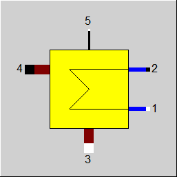
Display Option 2 |
 |
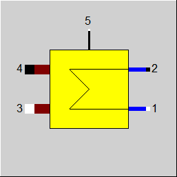
Display Option 3 |
 |
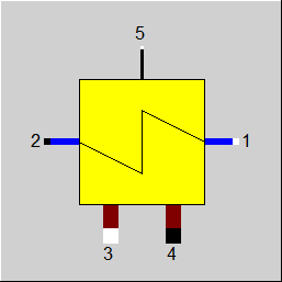
Display Option 4 |
 |
Display Option 5 |
 |
Display Option 6 |
 |
Display Option 7 |
 |
Display Option 8 |
 |
Display Option 9 |
 |
Display Option 10 |
 |
Display Option 11 |
 |
Display Option 12 |
 |
Display Option 13 |
 |
Display Option 14 |
Click here >> Component 61 Demo << to load an example.