EBSILON®Professional Online Documentation


|
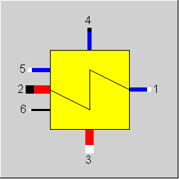
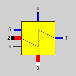
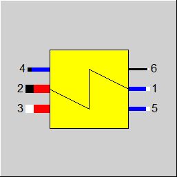
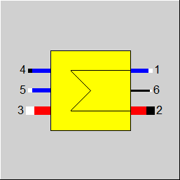
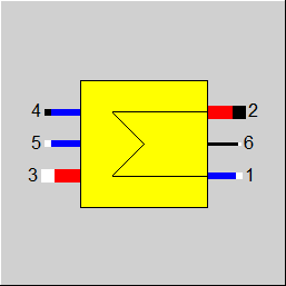
Line connections |
|
|
|
1 |
Primary inlet (cold stream, inside tubes) |
|
|
2 |
Primary outlet (cold stream, inside tubes) |
|
|
3 |
Secondary inlet (hot stream, outside tubes) |
|
|
4 |
Secondary outlet (hot stream, outside tubes) |
|
|
5 |
Auxiliary condensate inlet |
|
|
6 |
(K*A)-controlling inlet (Heat Transfer Capability) |
|
General User Input Values Characteristic Lines Physics Used Displays Example
Component 55 is a multi-purpose component that can be used instead of component 26 (Economizer, evaporator or super heater), component 25 (air preheater), component 27 (after-cooler) and - with additional controllers - instead of component 7 (condenser) and component 10 (preheater).
It differs from the components 25-27 in the following properties:
- A (k*A)-control connection (logic line 6) is available, which makes it possible to connect with the regulation components 12 or 39 (controllers with internal or external set values).
- Instead of the lower or the upper terminal temperature difference, the temperature T4 can be specified in the design case.
- In the off-design case, characteristic lines for the convective heat transfer coefficients on both sides of the tubes (AL12C, AL34C) are used, instead of the kA-characteristic lines.
It differs from component 51 in that there is no inlet of the auxiliary condensate and no consideration of the radiation.
The component can be calculated either with terminal temperature differences (see Heat Exchanger General ), in which case the related (k*A) is determined (design case), or else (k*A) is given, in which case the related terminal temperature differences are calculated. The third possibility is the controlling of (k*A). The type of calculation is selected with the specification value FMODE
The following possibilities are defined alternatively by FMODE:
FMODE=0
in design case (GLOBAL = design)
for off-design (GLOBAL = off-design)
FMODE=1
FMODE=2
FMODE=3
for design (GLOBAL = design)
for off-design (GLOBAL = off-design)
FMODE=4
for design and off-design (GLOBAL = Design and GLOBAL = Off-design)
Additional note to FMODE = 3/4
FMODE = 3 has be used to use the k * A control in design mode and to calculate a characteristic curve in the partial load.
FMODE = 4 it is always counted on k * A control, so reference values are not accepted.
The boundary conditions are defined from two characteristic lines, which are used only for GLOBAL = Off-design.
Characteristic line CKAM1: relative primary Heat Transfer Coefficient
AL12C/AL12CN = f (M1/M1N)
Characteristic line CKAM3: relative secondary Heat Transfer Coefficient
AL34C/AL34CN = f (M3/M3N)
If the terminal temperature differences are specified, it is important that depending upon the heat value (M*cp), either the lower or the upper terminal temperature difference leads to correct results.
There is an identification mode for this component: T4-default (FSPECD=3). Based on this default, k*A is calculated in all the load cases. In the design case, the terminal temperature difference is not used, in the off-design mode, KAN and the characteristic lines are not used.
Moreover, a threshold TOLXECO has been implemented, up to which an evaporation in the economizer is tolerated. If the steam mass fraction downstream of the economizer is greater than this threshold, a warning message will be output; if it is greater than twice this threshold, an error message will be output.
It is also possible for all components to use the flag FVOL to determine whether the off-design calculation of the pressure drop shall consider only the mass-flow (approximation for incompressible fluids) or mass and volume flow.
Pinch point violations in the case of heat exchangers: (see Heat Exchanger General )
Up to release 10.0, a pinchpoint violation was only determined subsequently in partial load, i.e. KA was calculated for the respective load case and from this the transferred heat quantity and then it was checked whether this heat quantity can be transferred at all at the correct temperature level. Since in the case of evaporation or condensation the temperature remains constant despite heat input or heat removal, there are cases where heat transfer is not physically possible despite the overall balance being correct. In this case, an error message was issued in Ebsilon.
The calculation has now been changed in such a way that the transferred heat quantity is reduced as far as it is still physically possible, with the minimum pinch point
can be set in a default value PINPMIN. This results in a correspondingly reduced KA.
The user is informed of this by a warning message ("KA reduced to avoid pinchpoint violation") and can then adjust the part-load characteristic curve or the part-load exponent for KA accordingly so that the warning no longer occurs. The advantage, however, is that one gets a physically possible result in any case.
Furthermore, at the end of the calculation there is a check if there is a pinch point violation due to curved course of Q(T) (caused by significant changes of cp depending on the temperature). This can be verified by dividing the heat exchanger into individual sections.
This case can occur, for example, when on the hot side the cp at the inlet is significantly smaller than at the outlet (for example, steam that has a cp of about 2 kJ/kgK at high superheat, but more than 5 just above the boiling line). This means that this steam provides more heat at a lower temperature level than at a high one. At appropriately low degrees, this can be a limitation on the amount of heat transfer that is possible.
The QT diagrams take into account the non-linearity (curvature of the curves) in areas without phase change.
The flag FSPEC (deprecated) has been divided into two flags:
Note:
When loading a model that was created with Release 11 (or older), the corresponding values for FTYPHX, FSPECD, are determined from the value of the flag FSPEC, and FSPEC is set to “void” (-999). The model then calculates the same result values. If required, however, the flag FSPEC can still be used as well.
To remove ambiguity, the terms “primary side” and “secondary side” respectively have been replaced by “cold side” and “warm side” in the input screens. The cold side is the flow from Pin 1 to Pin 2 that is heated. The warm side is the flow from Pin 3 to Pin 4 that gives off the heat.
Design in the Case of Concurrent Flow (see Heat Exchanger General )
In the heat exchanger (Components 55) it is possible to carry out a design via the upper and lower terminal temperature difference also in the case of concurrent flow (FFLOW=1).
If both inlet temperatures are specified, the upper terminal temperature difference can only be determined iteratively. Usually this is no problem. If convergence problems occur in more
complex models, another design mode will have to be used.
Effectiveness Method
See Heat Exchangers General Information Effectiveness Method
The effectiveness method is also available. Analogous to other heat exchangers, this option is selected via the switch FSPECD=0 . The effectiveness is also calculated in the heat exchanger calculation for other design methods (but not in the identification mode). For this purpose, a result value REFF was introduced.
REFF is the ratio of the heat actually transferred to the theoretical maximum that could be achieved with an infinitely large exchange surface. REFF depends on the size of the heat exchanger.
In the design case, the calculated effectiveness is also stored in the default value EFF when the reference values are adopted.
Specification of the surface area for designing heat exchanger (specification value AN)
Usually, heat exchangers are designed in Ebsilon by specifying the terminal temperature differences or temperatures to be achieved. In an iterative process, the transferred amount of heat and the product of heat transfer coefficient and surface area (k*A) characteristic for the heat exchanger are calculated from this. Its nominal value KAN then serves to calculate the temperatures in off-design calculations. It is not necessary to know the individual values k and A here.
In the case of the component Universal Heat Exchanger ( Component 55), the off-design behaviour is defined by exponents of heat transfer coefficients AL12 and AL34. As k can be calculated from it, the heat exchanger surface area A is available as well.
This has been used to implement a design calculation via the specification of the surface area. It is, however, essential to correctly specify the nominal values for the convective heat transfer coefficients AL12CN and AL34CN, which had only an effect on the partial load behaviour before to implementation of AN (area).
The specified surface area is only used for the design calculation to determine KAN from it. In the off-design calculation KAN is then used for the calculation.
Specific heat capacity : CP12 / CP34
The mean specific heat capacity is now displayed as result value on the cold side (CP12) and on the hot side (CP34).
The mean specific heat capacity results from the quotient of the enthalpy difference and the temperature difference.
If no temperature difference is present (e.g. in the two-phase range or when the heat exchanger is shut off), however, it is not possible to calculate this quotient. In this case, the specific heat capacity at the respective temperature is used, provided that it is defined. Otherwise the result value will remain blank.
Performance factor RPFHX
The quotient from the current value for k*A (result value KA) and the k*A expected in the respective load point due to the component physics and characteristic lines respectively (result value KACL) serves to assess the condition of a heat exchanger.
The quotient KA / KACL is displayed as a result value RPFHX.
For more information on general notes applicable to most common heat exchangers, see Heat Exchanger General Notes
Für weitere allgemeine Informationen mit Bezug zu den meisten üblichen Wärmetauschern siehe Wärmetauscher, allgemeine Anmerkungen
For more general information with reference to most common heat exchangers, see Heat exchanger, general notes.
The (k*A)-value for the off-design mode results from the (k*A)-value of the design calculation multiplied with a correction factor. This is defined by one or more characteristic lines. The following calculation mode serves as the basis:
AL12C/AL12CN = f (M1 /M1N ) characteristic line CKAM1
AL34C/AL34CN = f (M3 /M3N ) characteristic line CKAM3
1/K = 1/AL12C + 1/AL34C
1/KN = 1/AL12CN + 1/AL34CN
k*A=(k*A)N * K/KN
for design calculations:
The characteristic lines can be corrected or replaced by an adaption polynomial or a Kernel expression.
|
FTYPHX |
Type of heat exchanger Like in Parent Profile (Sub Profile option only) Expression = 0: General heat exchanger |
|
FSPECD |
Calculation method in design-case Like in Parent Profile (Sub Profile option only) Expression = 0: Specification of the effectiveness (ratio of transferred heat to the theoretical maximum at infinite transfer surface) in the specification value EFF |
|
DTN |
Terminal temperature difference or temperature in design mode (nominal, dependent on FSPEC) for FSPECD=1: lower terminal temperature difference (T4 - T1) for FSPECD=2: upper terminal temperature difference (T3 - T2) for FSPECD=3: T4 |
|
EFF |
Effectiveness |
|
AN |
Heat transfer area (nominal) , for FSPECD = 9 |
|
DP12N |
Cold side pressure loss (nominal) [absolute] |
|
DP34N |
Hot side pressure loss (nominal) [absolute] |
|
TOL |
Tolerance in the energy balance |
|
AL12CN |
Cold side convection heat-transfer coefficient (nominal) |
|
AL34CN |
Hot side convection heat-transfer coefficient (nominal) |
|
FMODE |
Calculation modE Like in Parent Profile (Sub Profile option only) Expression =0: GLOBAL =1: Local off-design =2: Special local off-design (see above) =3: (Design) Use of K*A regulated, (off-design) alpha-characteristic line =4: All modes: Use of K*A regulated =-1: Local design |
|
FFLOW |
Switch for direction of flow (see Heat Exchanger General ), Like in Parent Profile (Sub Profile option only) Expression =0: counter current =1: concurrent |
|
FVOL |
Volume dependency of pressure losses Like in Parent Profile (Sub Profile option only) Expression =0: no consideration of the volume dependency DP/DPN = (M/MN)**2 =1: consideration of the volume and mass flow dependency DP/DPN = V/VN*(M/MN)**2 =2: constant pressure drop (no load dependency) |
|
FADAPT |
Flag for adaptation polynomial ADAPT / adaptation function EADAPt Expression =0: Not used and not evaluated =1: Correction for k*A [KA = KAN * Char Line factor * polynomial] =2: Calculation of k*A [KA = KAN * polynomial] =1000: Not used but ADAPT evaluated as RADAPT (Reduction of the computing time)
= -1: Correction for k*A [KA = KAN * Char Line factor * adaptation function] = -2: Calculation of k*A [KA = KAN * adaptation function] = -1000: Not used but EADAPT evaluated as RADAPT (Reduction of the computing time) |
|
EADAPT |
Adaptation function for KA |
|
FFU |
Switch on/off Expression =0: Heat exchanger off (no heat transfer, but calculation of pressure losses) =1: Heat exchanger on (active) |
|
PINPMIN |
Minimum value for the pinch point (KA is reduced automatically if the pinch point would fall below this value) |
|
TOLXECO |
Tolerance for evaporation in an economizer. If the steam content X at the economizer outlet is > TOLXECO, a warning message is issued. If it is > 2*TOLXECO, an error message is issued. |
|
FSPEC (deprecated) |
Deprecated specification combi switch Like in Parent Profile (Sub Profile option only) Expression = -999: Unused (FSPECD and FIDENT used instead) Old values: =1: General heat-exchanger, user specifies lower terminal temperature difference =2: General heat-exchanger, user specifies upper terminal temperature difference =3: General heat-exchanger, user specifies T4 =11: Economizer, user specifies lower terminal temperature difference =12: Economizer, user specifies upper terminal temperature difference =13: Economizer, user specifies T4 =21: Evaporator, user specifies lower terminal temperature difference =22: Evaporator, user specifies upper terminal temperature difference =23: Evaporator, user specifies T4 =31: Super Heater, user specifies lower terminal temperature difference =32: Super Heater, user specifies upper terminal temperature difference =33: Super Heater, user specifies T4 |
|
KAN |
k*A (nominal) - Design Heat Transfer Capability |
|
M1N |
Primary mass flow(nominal) |
|
M3N |
Secondary mass flow(nominal) |
|
V1N |
Specific volume for primary inlet (nominal) |
|
V3N |
Specific value for secondary inlet (nominal) |
The parameters marked in blue are reference quantities for the off-design mode. The actual off-design values refer to these quantities in the equations used.
Generally, all inputs that are visible are required. But, often default values are provided.
For more information on colour of the input fields and their descriptions see Edit Component\Specification values
For more information on design vs. off-design and nominal values see General\Accept Nominal values
1st Characteristic line CKAM1 FK1 = AL12C/AL12CN = f (M1/M1N)
2nd Characteristic line CKAM3 FK2 = AL34C/AL34CN = f (M3/M3N)
1/K = 1/AL12C + 1/AL34C
1/KN = 1/AL12CN + 1/AL34CN
k*A = KAN * K/KN
|
Characteristic line 1 CKAM1: ALPHA-characteristic line: AL12C/AL12CN = f (M1/M1N) |
|
X-axis 1 M1/M1N 1st point 2 M1/M1N 2nd point . N M1/M1N last point Y-axis 1 AL12C/AL12CN 1st point |
|
Characteristic line 2 CKAM3: ALPHA-characteristic line: AL34C/AL34CN = f (M3/M3N) |
| X-axis 1 M3/M3N 1st point 2 M3/M3N 2nd point . N M3/M3N last point Y-axis 1 AL34C/AL34CN 1st point 2 AL34C/AL34CN 2nd point . N AL34C/AL34CN last point |
|
Design (Simulation flag: GLOBAL = Design and FMODE = Design) |
||
|
|
If the lower terminal temperature difference is given by FSPEC, then {
P4 = P3 - DP34N T4 = T1 + DTN H4 = f(P4,T4) M4 = M3 Q4 = M4 * H4 DQ = (Q3 - Q4) P2 = P1 - DP12N Q2 = Q1 + DQ M2 = M1 H2 = Q2/M2 T2 = f(P2,H2) DTLO = T4 - T1 (for FFLOW = counter current) DTUP = T3 - T2 (for FFLOW = counter current) LMTD = (DTUP - DTLO)/(ln(DTUP) - ln(DTLO)) KAN = DQ/LMTD KAN*LMTD = M2*H2 - M1*H1 KAN*LMTD = M3*H3 - M4*H4 } if the upper terminal temperature difference is given by FSPEC, then { P2 = P1 - DP12N T2 = T3 - DTN M2 = M1 H2 = f(P2,T2) Q2 = M2 * H2 DQ = Q2 - Q1 P4 = P3 - DP34N Q4 = Q3 - DQ M4 = M3 H4 = Q4/M4 T4 = f(H4,P4) DTLO = T4 - T1 (for FFLOW = counter current) DTUP = T3 - T2 (for FFLOW = counter current) LMTD = (DTUP - DTLO)/(ln(DTUP) - ln(DTLO)) KAN = DQ/LMTD KAN*LMTD = M2*H2 - M1*H1 KAN*LMTD = M3*H3 - M4*H4 } if the temperature T4 is specified with FSPEC, then { P4 = P3 - DP34N T4 = DTN H4 = f(P4,T4) M4 = M3 Q4 = M4 * H4 DQ = Q3 - Q4 P2 = P1 - DP12N Q2 = Q1 + DQ M2 = M1 H2 = Q2/M2 T2 = f(P2,H2) DTLO = T4 - T1 (for FFLOW = counter current) DTUP = T3 - T2 (for FFLOW = counter current) LMTD = (DTUP - DTLO)/(ln(DTUP) - ln(DTLO)) KAN = DQ/LMTD KAN*LMTD = M2*H2 - M1*H1 KAN*LMTD = M3*H3 - M4*H4 } |
|
|
Off-design (Simulation flag: GLOBAL = Off-design or FMODE = off-design) |
||
|
|
if FVOL = without, then {
F1 = (M1/M1N) ** 2 if FMODE=1, then F1=1.0
F3 = (M3/M3N) ** 2 if FMODE=1, then F3=1.0 }
if FVOL= with, then {
F1 = V1/V1N*(M1/M1N) ** 2 if FMODE=1, then F1=1.0
F3 = V3/V3N*(M3/M3N) ** 2 if FMODE=1, then F3=1.0 }
P2 = P1 - DP12N * F1 M2 = M1
if GLOBAL = off-design or (FMODE = 1 or FMODE = 3), then {
Fk1 = f(M1/M1N) characteristic line 1 for MODE = Design, Fk1=1
Fk2 = f(M3/M3N) characteristic line 2 for MODE = Design, Fk2=1
1/KN = 1/AL12CN + 1/AL34CN 1/K = 1/(AL12CN*Fk1) + 1/(AL34CN*Fk2)
KA=KAN * K/KN }
if GLOBAL = Design and (FMODE = 3 or FMODE = 4), then { KA = H6 (controlled) }
if GLOBAL = off-design and FMODE = 4, then { KA = H6 (controlled) }
P4 = P3 - DP34N * F3 M4 = M3 + M5
Maximum/minimum values for the iterations { H2max = f(P2,T3) Q12max = M1 * (H2max - H1) H4min = f(P4,T1) Q34max = Q3 - M4 * H4min }
for FFLOW = counter current { Qmax = min(Q12max,Q34max) }
for FFLOW = concurrent { Estimation for iteration start 1 QA = min(Q12max,Q34max) QM = QA*QA/(Q12max+Q34max)
Iteration1{ H2 = H1 + QM/ M2 T2 = f(P2,H2) T4 = T2 H4 = f(P4,T4) QK = Q3 -M4 * H4 DQQ_1 = DQQ DQQ = QM - QK regula - falsi method { Size = (QM - QM_1)/(DQQ - DQQ_1) for iteration step 1: size of the last global step QMU = QM - DQQ * size QM_1 = QM QM = QMU } DQ = | DQQ/((QM+QK)*.5) |
if DQ < TOL, then end iteration 1 , else continue the iteration } Qmax = QM }
Q12 = 0.5*Qmax
Iteration2{ H4 = (Q3 - Q12)/M4 T4 = f(P4,H4) H2 = H1 + Q12/M2 T2 = f(P2,H2)
DTLO = T4 - T1 (for FFLOW = counter current) DTUP = T3 - T2 (for FFLOW = counter current)
DTLO = T4 T2 (for FFLOW = concurrent) DTUP = T3 T1 (for FFLOW = concurrent)
LMTD = (DTUP - DTLO)/(ln(DTUP) - ln(DTLO))
QQ = KA * LMTD DQQ_1 = DQQ DQQ = Q12 - QQ
regula - falsi method { Size = (Q12 - Q12_1)/(DQQ - DQQ_1) for iteration step 1: size of the last global step Q12X = Q12 - DQQ * Size Q12_1 = Q12 Q12 = Q12X }
DQ = |DQQ /((Q12+QQ)*.5)| if DQ < TOL, then end iteration 2 else continue the iteration } KA*LMTD = M2*H2 - M1*H1 KA*LMTD = M3*H3 - M4*H4 |
|
 |
Display Option 1 |
 |
Display Option 2 |
 |
Display Option 3 |
 |
Display Option 4 |
 |
Display Option 5 |
 |
Display Option 6 |
 |
Display Option 7 |
 |
Display Option 8 |
 |
Display Option 9 |
 |
Display Option 10 |
 |
Display Option 11 |
 |
Display Option 12 |
 |
Display Option 13 |
 |
Display Option 14 |
Click here >> Component 55 Demo << to load an example.