
EBSILON®Professional Online Documentation


|
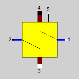
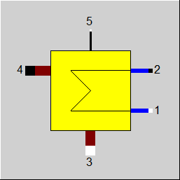
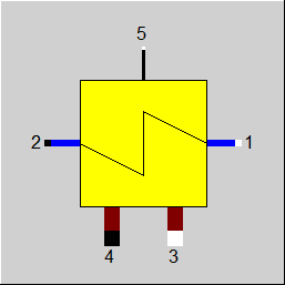
Line connections |
|
|
|
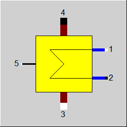
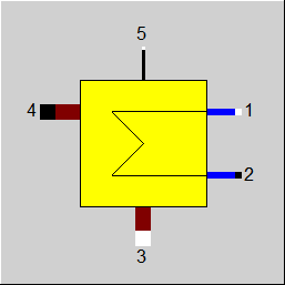
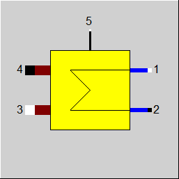
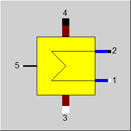
1 |
Primary inlet (colder stream, inside tubes) |
|
|
2 |
Primary outlet (colder stream, inside tubes) |
|
|
3 |
secondary inlet (hotter stream, outside tubes) |
|
|
4 |
Secondary outlet (hotter stream, outside tubes) |
|
|
5 |
Control inlet for KAN - Design Heat Transfer Capability (as H) |
|
General User Input Values Characteristic Lines Physics Used Displays Example
Module 26 is a multi-purpose module that can be inserted as Economizer, evaporator or super heater. It can be used generally to model any heat exchanger.
For more information on general notes applicable to most common heat exchangers, see Heat Exchanger General Notes
The (k*A)-value of the off-design calculation results from the (k*A)-value of the design calculation multiplied by a correction factor that is determined by one or more characteristic lines. The corrections of the characteristic lines indicate the dependency of the k-number of the primary and secondary mass flow.
A kernel expression can be used as a supplement or alternative to the adaptation polynomial. The control is effected via the Flag FADAPT.
Radiation losses can be entered as loss factor.
In the case of this component, the design via an effectiveness factor is possible. It refers to the theoretically possible maximum heat exchange (for an infinitely large heat exchanger surface area). Thus an effectiveness of 0.8 means that 80 percent of the theoretically possible heat is exchanged.
If the terminal temperature differences are specified, it is important that depending upon the heat value (M*cp), either the lower or the upper terminal temperature difference ( see Heat Exchanger General Notes ) leads to correct results.
When using complex cycle arrangements for heat exchangers, it is often not easy to determine the settings of all terminal temperature differences in a useful manner. Error messages occur frequently because an inoperable heat exchanger may also cause some errors in other heat exchangers. To avoid this (k*A) can be entered instead of terminal temperature differences. This can be done in the design mode by using the mode "local off-design". An input of (k*A) always leads to physically possible results. The desired result can be determined through iterative
calculations with different (k*A) values.
There are two identification modes for this component: T2-default (FIDENT=2) and T4-default (FIDENT=4). Based on this default, k*A is calculated in all the load cases. In the design case, the terminal temperature difference is not used, in the off-design mode, KAN and the characteristic lines are not used.
Moreover, a threshold TOLXECO has been implemented, up to which an evaporation in the economizer is tolerated. If the steam mass fraction downstream of the economizer is greater than this threshold, a warning message will be output; if it is greater than twice this threshold, an error message will be output.
For this heat exchanger it is possible, to specify the pressure externally (P2, P4).
It is also possible to use the flag FVOL to determine whether the off-design calculation of the pressure drop shall consider only the mass-flow (approximation for incompressible fluids) or mass
and volume flow.
Logic inlet (Connection point 5) for controlling component properties
(see also : Editing components --> Ports)
To make component properties like efficiencies or heat transfer coefficients (variation quantity) accessible from the outside (for control or reconciliation) it is possible to place the respective value on an auxiliary line as an indexed measured value (specification value FIND). In the component, the same index must then be entered as specification value IPS.
It is also possible to place this value on a logic line that is directly connected to the component (please see FVALKA=2, Variation variable: KAN, Dimension: Enthalpy).
The advantage is that the allocation is now graphically visible, and errors (e.g. when copying) are thus avoided.
Pinch point violations in the case of heat exchangers: (See "Heat Exchanger General")
Up to release 10.0, a pinchpoint violation was only determined subsequently in partial load, i.e. KA was calculated for the respective load case and from this the transferred heat quantity and then it was checked whether this heat quantity can be transferred at all at the correct temperature level. Since in the case of evaporation or condensation the temperature remains constant despite heat input or heat removal, there are cases where heat transfer is not physically possible despite the overall balance being correct. In this case, an error message was issued in Ebsilon.
The calculation has now been changed in such a way that the transferred heat quantity is reduced as far as it is still physically possible, with the minimum pinch point
can be set in a default value PINPMIN. This results in a correspondingly reduced KA.
The user is informed of this by a warning message ("KA reduced to avoid pinchpoint violation") and can then adjust the part-load characteristic curve or the part-load exponent for KA accordingly so that the warning no longer occurs. The advantage, however, is that one gets a physically possible result in any case.
Furthermore, at the end of the calculation there is a check if there is a pinch point violation due to curved course of Q(T) (caused by significant changes of cp depending on the temperature). This can be verified by dividing the heat exchanger into individual sections.
This case can occur, for example, when on the hot side the cp at the inlet is significantly smaller than at the outlet (for example, steam that has a cp of about 2 kJ/kgK at high superheat, but more than 5 just above the boiling line). This means that this steam provides more heat at a lower temperature level than at a high one. At appropriately low degrees, this can be a limitation on the amount of heat transfer that is possible.
The QT diagrams take into account the non-linearity (curvature of the curves) in areas without phase change.
The flag FSPEC (deprecated) has been divided into three flags:
Note:
When loading a model that was created with Release 11 (or older), the corresponding values for FTYPHX, FSPECD, and FIDENT are determined from the value of the flag FSPEC, and FSPEC is set to “void” (-999). The model then calculates the same result values. If required, however, the flag FSPEC can still be used as well. This is necessary so that the existing EbsScripts in which a switchover of FSPEC into an identification mode is carried out will continue working. If FSPEC is not “empty” (-999) but has a value of -4 or -5 (the old values for the identification modes),
the new flag FIDENT will be ignored, and the component will behave according to the setting of FSPEC (this is indicated in a comment).
To remove ambiguity, the terms “primary side” and “secondary side” respectively have been replaced by “cold side” and “warm side” in the input screens. The cold side is the flow from
Pin 1 to Pin 2 that is heated. The warm side is the flow from Pin 3 to Pin 4 that gives off the heat.
Design in the Case of Concurrent Flow see Heat Exchanger General Notes
In the heat exchanger (Components 26) it is possible to carry out a design via the upper and lower terminal temperature difference also in the case of concurrent flow (FFLOW=1).
If both inlet temperatures are specified, the upper terminal temperature difference can only be determined iteratively. Usually this is no problem. If convergence problems occur in more
complex models, another design mode will have to be used.
Effectiveness Method
See Heat Exchangers General Information Effectiveness Method
Flag FDQLR
It is possible, you can use the FDQLR flag to define how DQLR (factor for modeling heat losses) should be interpreted.
Specific heat capacity : CP12 / CP34
The mean specific heat capacity is now displayed as result value on the cold side (CP12) and on the hot side (CP34).
The mean specific heat capacity results from the quotient of the enthalpy difference and the temperature difference.
If no temperature difference is present (e.g. in the two-phase range or when the heat exchanger is shut off), however, it is not possible to calculate this quotient. In this case, the specific heat capacity at the respective temperature is used, provided that it is defined. Otherwise the result value will remain blank.
Performance factor RPFHX
The quotient from the current value for k*A (result value KA) and the k*A expected in the respective load point due to the component physics and characteristic lines respectively (result value KACL) serves to assess the condition of a heat exchanger.
The quotient KA / KACL is displayed as a result value RPFHX.
For more information on how this heat exchangers compares to other heat exchangers, see Heat Exchanger General Components
|
FTYPHX |
Type of heat exchanger Like in Parent Profile (Sub Profile option only) Expression = 0: General heat exchanger |
|
FSPECD |
Calculation method in design-case Like in Parent Profile (Sub Profile option only) Expression = 0: Specification of the effectiveness (ratio of transferred heat to the theoretical maximum at infinite transfer surface) in the specification value EFF
|
|
FIDENT |
Activation of a component identification mode (only in part load) (FIDENT serves to activate a component identification mode, i.e. the respective condition of the component is determined on the basis of temperature specifications) Like in Parent Profile (Sub Profile option only) Expression = 0: No identification mode In the design case, variant FIDENT=2 is identical with FSPECD=5 and FIDENT=4 with FSPECD=4. In order to prevent contradictory specifications, the flag FIDENT is therefore only used in off-design for this component. Please note: the peculiarity for these components is that in the design case identification (namely the calculation of KAN from temperature specifications) takes place by default.
|
|
DTN |
Terminal temperature difference (nominal) Depending upon the value of FSPECD, either the upper (=T3-T2) or the lower (=T4-T1) terminal temperature difference is to be entered here. |
|
EFF |
Effectiveness |
|
FDP12N |
Pressure drop handling line 1 to 2 Like in Parent Profile (Sub Profile option only) Expression =1: Calculated by DP12N |
|
DP12N |
Cold side pressure drop (nominal) |
|
FDP34N |
Pressure drop handling line 3 to 4 Like in Parent Profile (Sub Profile option only) Expression =1: Calculated by DP34N |
|
DP34N |
Hot side pressure drop (nominal) |
|
FVOL |
Flag for partload pressure drop Like in Parent Profile (Sub Profile option only) Expression =0: Only depending on mass flow =1: Depending on mass- and volume flow |
|
FDQLR |
Heat loss handling Like in Parent Profile (Sub Profile option only) Expression =0: Constant (DQLR*QN in all load cases) |
|
DQLR |
Heat loss through radiation (relative to QN) |
|
TOL |
Maximum permissible tolerance in energy balance for the internal iteration |
|
FMODE |
Flag for the calculation mode design/off-design Like in Parent Profile (Sub Profile option only) Expression =0: Global =1: local off-design (i.e. always off-design mode, even when a design calculation has been done globally) =2: special local off-design (Special case for compatibility with the earlier Ebsilon-versions, should not be used in new models, because the results of the real off-design calculations are not always consistent) = -1: local design |
|
FFLOW |
Flag for the direction of flow , see Heat Exchanger General Notes Like in Parent Profile (Sub Profile option only) Expression =0: Counter Current flow =1: Concurrent flow =2: Cross flow |
|
NROW |
Number of rows (for cross flow) |
|
NPASS |
Number of passes (for cross flow) |
|
FARR |
Arrangement of passes Like in Parent Profile (Sub Profile option only) Expression =0: Counter Current flow =1: Concurrent flow |
|
FADAPT
|
Flag for adaptation polynomial ADAPT/ adaptation function EADAPT Like in Parent Profile (Sub Profile option only) Expression =0: Not used and not evaluated =1: Correction for k*A [KA = KAN * carline factor * polynomial] =2: Calculation of k*A [KA = KAN * polynomial] =1000: Not used but ADAPT evaluated as RADAPT (Reduction of the computing time)
= -1: Correction for k*A [KA = KAN * carline factor * adaptation function] = -2: Calculation of k*A [KA = KAN * adaptation function] = -1000: Not used but EADAPT evaluated as RADAPT (Reduction of the computing time) |
|
EADAPT |
Adaptation function for KA |
|
FFU |
Flag on/off Like in Parent Profile (Sub Profile option only) Expression =0: Heat exchanger deactivated (no heat transfer, but pressure losses) =1: Heat exchanger on (active) |
|
FVALKA |
Validation of k*A (only in off-design) Like in Parent Profile (Sub Profile option only) Expression =0: fixed definition through KAN (without validation) =1: specified through pseudo measurement point IPS (can be validated) =2: KAN given by enthalpy on control inlet 5 |
|
IPS |
Index on the pseudo measurement point |
|
PINPMIN |
Minimum value for the pinch point (KA is reduced automatically if the pinch point would fall below this value) |
|
TOLXECO |
Tolerance for evaporation in an economizer. If the steam content X at the economizer outlet is > TOLXECO, a warning message is issued. If it is > 2*TOLXECO, an error message is issued. |
|
FSPEC (deprecated) |
Deprecated specification combi switch Like in Parent Profile (Sub Profile option only) Expression = -999: Unused (FSPECD and FIDENT used instead) Old values: =0: General heat exchanger: effectiveness method =1: General heat exchanger: In the design case, user enters lower terminal temperature difference (DT41N), calculation is done in off-design mode with characteristic lines =2: General heat exchanger: In the design case, user enters upper terminal temperature difference (DT32N), calculation is done in off-design mode with characteristic lines =4: General heat exchanger: In the design case T3 and T4 as well as one of the two temperatures T1 or T2 are determined outside this component, in off-design case calculation is done with characteristic lines =5: General heat exchanger: In the design case T1 and T2 as well as one of the two temperatures T3 or T4 are determined outside this component, in off-design case calculation is done with characteristic lines =10: Economizer, effectiveness method =11: Economizer: In the design case, user enters lower terminal temperature difference (DT41N), calculation is done in off-design mode with characteristic lines =12: Economizer: In the design case, user enters upper terminal temperature difference (DT32N), calculation is done in off-design mode with characteristic lines =14: Economizer: In the design case T3 and T4 as well as one of the two temperatures T1 or T2 are determined outside this component, in off-design case calculation is done with characteristic lines =15: Economizer: In the design case T1 and T2 as well as one of the two temperatures T3 or T4 are determined outside this component, in off-design case calculation is done with characteristic lines =20: Evaporator, effectiveness method =21: Evaporator: In the design case, user enters lower terminal temperature difference (DT41N), calculation is done in off-design mode with characteristic lines =22: Evaporator: In the design case, user enters upper terminal temperature difference (DT32N), calculation is done in off-design mode with characteristic lines =24: Evaporator: In the design case T3 and T4 as well as one of the two temperatures T1 or T2 are determined outside this component, in off-design case calculation is done with characteristic lines =25: Evaporator: In the design case T1 and T2 as well as one of the two temperatures T3 or T4 are determined outside this component, in off-design case calculation is done with characteristic lines =30: Super Heater: effectiveness method =31: Super Heater: In the design case, user enters lower terminal temperature difference (DT41N), calculation is done in off-design mode with characteristic lines =32: Super Heater: In the design case, user enters upper terminal temperature difference (DT32N), calculation is done in off-design mode with characteristic lines =34: Super Heater: In the design case T3 and T4 as well as one of the two temperatures T1 or T2 are determined outside this component, in off-design case calculation is done with characteristic lines =35: Super Heater: In the design case T1 and T2 as well as one of the two temperatures T3 or T4 are determined outside this component, in off-design case calculation is done with characteristic lines = -5: Identification mode for all operation modes: T2 is determined outside this component (in all load cases), DTN or characteristic lines are not used = -4: Identification mode for all operation modes: T4 is determined outside this component (in all load cases), DTN or characteristic lines are not used |
|
KAN |
Heat transfer coefficient * area (nominal) - Design Heat Transfer Capability |
|
M1N |
Cold side mass flow (nominal) |
|
M3N |
Hot side mass flow (nominal) |
|
QN |
Heat exchanger power (nominal) (Q34N) |
|
V1N |
Specific volume at primary inlet (nominal) |
|
V3N |
Specific volume at secondary inlet (nominal) |
The parameters marked in blue are reference quantities for the off-design mode. The actual off-design values refer to these quantities in the equations used.
Generally, all inputs that are visible are required. But, often default values are provided.
For more information on colour of the input fields and their descriptions see Edit Component\Specification values
For more information on design vs. off-design and nominal values see General\Accept Nominal values
The following medium combinations are allowed:
|
Primär |
Sekundär |
|
Water, Steam |
Air, Flue gas, Steam, Water, Crude gas, Oil, Gas, User-defined, 2-Phase liquid, 2-Phase gaseous, Saltwater, Universal fluid, Binary mixture, Thermo liquid |
|
2-Phase (liquid, gaseuos) |
Air, Flue gas, Steam, Water, Crude gas, Oil, Gas, User-defined, 2-Phase liquid, 2-Phase gaseous, Saltwater, Universal fluid, Binary mixture, Thermo liquid |
| Saltwater | Air, Flue gas, Steam, Water, Crude gas, Oil, Gas, User-defined, 2-Phase liquid, 2-Phase gaseous, Saltwater, Universal fluid, Binary mixture, Thermo liquid |
| Universal fluid | Air, Flue gas, Steam, Water, Crude gas, Oil, Gas, User-defined, 2-Phase liquid, 2-Phase gaseous, Saltwater, Universal fluid, Binary mixture, Thermo liquid |
| Binary mixture | Air, Flue gas, Steam, Water, Crude gas, Oil, Gas, User-defined, 2-Phase liquid, 2-Phase gaseous, Saltwater, Universal fluid, Binary mixture, Thermo liquid |
| Thermo liquid | Air, Flue gas, Steam, Water, Crude gas, Oil, Gas, User-defined, 2-Phase liquid, 2-Phase gaseous, Saltwater, Universal fluid, Binary mixture, Thermo liquid |
1st characteristic line CKAM1 FK1 = f (M1/M1N)
2nd characteristic line CKAM3 FK2 = f (M3/M3N)
(k*A) / (k*A)N = FK1 * FK2
|
Characteristic line 1: (k*A)-characteristic line CKAM1: (k*A)1/(k*A)N = f (M1/M1N) |
|
X-axis 1 M1/M1N 1st point |
|
Characteristic line2: (k*A)-characteristic line CKAM3: (k*A)2/(k*A)N = f (M3/M3N) |
|
X-axis 1 M3/M3N 1st point |
|
Design case (Simulation flag: GLOBAL = Design case and FMODE = design case) |
||
|
|
if the lower temperature difference is given by FSPEC, then { P4 = P3 - DP34N T4 = T1 + DTN H4 = f(P4,T4) M4 = M3 Q4 = M4 * H4 DQ = (Q3 - Q4)*(1-DQLR)
P2 = P1 - DP12N Q2 = Q1 + DQ M2 = M1 H2 = Q2/M2 T2 = f(P2,H2)
DTLO = T4 - T1 (for FFLOW = counter current) DTUP = T3 - T2 (for FFLOW = counter current)
LMTD = (DTUP - DTLO)/(ln(DTUP) - ln(DTLO)) KAN = DQ/LMTD
KAN*LMTD = M2*H2 - M1*H1 KAN*LMTD = (M3*H3 - M4*H4)*(1 - DQLR) } if the upper temperature difference is given by FSPEC, then { P2 = P1 - DP12N T2 = T3 - DTN M2 = M1 H2 = f(P2,T2) Q2 = M2 * H2 DQ = Q2 - Q1
P4 = P3 - DP34N Q4 = Q3 - DQ/(1 - DQLR) M4 = M3 H4 = Q4/M4 T4 = f(H4,P4)
DTLO = T4 - T1 (for FFLOW = counter current) DTUP = T3 - T2 (for FFLOW = counter current) LMTD = (DTUP - DTLO)/(ln(DTUP) - ln(DTLO)) KAN = DQ/LMTD
KAN*LMTD = M2*H2 - M1*H1 KAN*LMTD = (M3*H3 - M4*H4)*(1 - DQLR) } |
|
|
Off-design case (Simulation flag: GLOBAL = Off-design or FMODE = off-design) |
||
|
|
F1 = (M1/M1N) ** 2 if GLOBAL = design, then F1=1.0
F3 = (M3/M3N) ** 2 if GLOBAL = design, then F3=1.0
P2 = P1 - DP12N * F1 M2 = M1
FK1 = f(M1/M1N) from characteristic line 1 if GLOBAL = design, then FK1=1.0
FK2 = f(M3/M3N) from characteristic line 2 if GLOBAL = design, then FK2=1.0
KA = KAN * FK1 * FK2
P4 = P3 - DP34N * F3 M4 = M3
Maximum/Minimum values for the iteration { H2max = f(P2,T3) Q12max = M1 * (H2max - H1) H4min = f(P4,T1) Q34max = Q3 - M4 * H4min } For FFLOW = counter current { Qmax = min(Q12max,Q34max) }
In case of FFLOW = concurrent { Estimation before starting the iteration 1 QA = min(Q12max,Q34max) QM = QA*QA/(Q12max+Q34max)
iteration1{ H2 = H1 + QM*(1-DQLR)/ M2 T2 = f(P2,H2) T4 = T2 H4 = f(P4,T4) QN = Q3 -M4 * H4 DQQ_1 = DQQ DQQ = QM - QN Regula - falsi method { grade = (QM - QM_1)/(DQQ - DQQ_1) at iteration step 1: Gradient of the last global step QMN = QM - DQQ * grade QM_1 = QM QM = QMN } DQ = | DQQ/((QM+QN)*.5) |
if DQ < TOL, then end iteration 1 else continue the iteration } Qmax = QM } Q12 = 0.5*Qmax Iteration2{ H4 = (Q3 - Q12/(1-DQLR) )/M4 T4 = f(P4,H4) H2 = H1 + Q12/M2 T2 = f(P2,H2)
DTLO = T4 - T1 (for FFLOW = counter current) DTUP = T3 - T2 (for FFLOW = counter current)
DTLO = T4 T2 (for FFLOW = concurrent) DTUP = T3 T1 (for FFLOW = concurrent)
LMTD = (DTUP - DTLO)/(ln(DTUP) - ln(DTLO))
QQ = KA * LMTD DQQ_1 = DQQ DQQ = Q12 - QQ
Regula - falsi method { grade = (Q12 - Q12_1)/(DQQ - DQQ_1) at iteration step 1: Gradient of the last global step Q12X = Q12 - DQQ * grade Q12_1 = Q12 Q12 = Q12X } DQ = |DQQ /((Q12+QQ)*.5)| if DQ < TOL, then end iteration 2 else continue the iteration } QN = Q3 -M4 * H4
KA*LMTD = M2*H2 - M1*H1 KA*LMTD = M3*H3 - M4*H4 - QN*DQLR |
|
 |
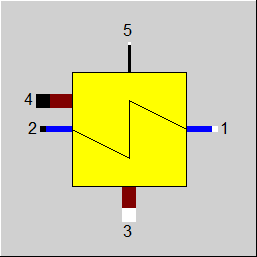
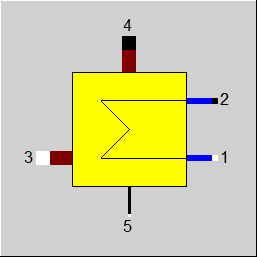
Display Option 1 |
 |
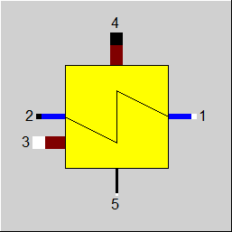
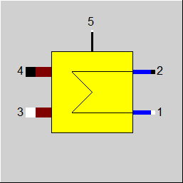
Display Option 2 |
 |
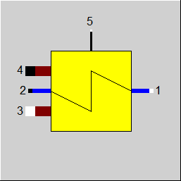
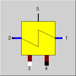
Display Option 3 |
 |
Display Option 4 |
 |
Display Option 5 |
 |
Display Option 6 |
 |
Display Option 7 |
 |
Display Option 8 |
 |
Display Option 9 |
 |
Display Option 10 |
 |
Display Option 11 |
 |
Display Option 12 |
 |
Display Option 13 |
 |
Display Option 14 |
Click here >> Component 26 Demo << to load an example.