EBSILON®Professional Online Documentation


|
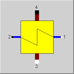
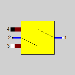
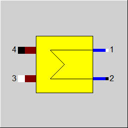
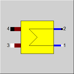
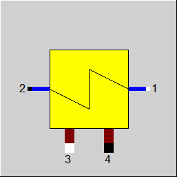
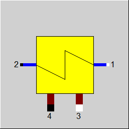
Line connections |
|
|
|
1 |
Primary inlet, (cold stream, inside tubes)) |
|
|
2 |
Primary outlet (cold stream, outside tubes) |
|
|
3 |
Secondary inlet (hot stream, flue gas, outside tubes) |
|
|
4 |
Secondary outlet (hot stream, flue gas, outside tubes) |
|
General User Input Values Characteristic Lines Physics Used Displays Example
Component 73 is a multi-purpose component, which can be used as Economizer, Evaporator or as Super Heater.
It differs from component 26 in the method of calculation of the heat transfer capability (k*A-values) in the off-design mode. Component 26 takes a characteristic line as a basis, whereas component 61 uses the relationships of the individual heat transfer coefficients.
It especially differs from component 61 with respect to a specific fin-efficiency calculation. (VDI Heat Atlas, Mb 4)
The module can either calculate with terminal temperature differences (see: Heat Exchanger General Notes ), in which case the corresponding (k*A) will be determined, or with a given (k*A), in which case the corresponding terminal temperature difference will be determined. The first or the second type of calculation can be selected by the specification value FMODE.
For the off-design behaviour of k*A, an EbsScript function in the specification field EADAPT can be used as an alternative to the adaptation polynomial ADAPT.
The component can be deactivated with the switch FFU. In that case, heat is no longer exchanged, but pressure losses are still taken into account.
Radiation losses DQLR can defined by means of a loss factor.
Pressure drop limitations in off-design (Extras --> Model Options--> Calculation -->Relative pressure-drop maximum) :
As the pressure drop rises quadratically with the mass flow, pressure drops that are significantly too high can quickly arise in the event of a transgression of the nominal mass flow. These will then cause phase transitions and convergence problems. For this reason, pressure drop limitations have been installed.
Constant pressure loss (FVOL=2):
For these components, it is possible to specify a constant pressure drop. This is especially helpful when the pressure drop is known for a certain part load point (from measurement, e.g.) or you want to use your own formula for the pressure drop.
Pinch point violations in the case of heat exchangers:
Up to release 10.0, a pinchpoint violation was only determined subsequently in partial load, i.e. KA was calculated for the respective load case and from this the transferred heat quantity and then it was checked whether this heat quantity can be transferred at all at the correct temperature level. Since in the case of evaporation or condensation the temperature remains constant despite heat input or heat removal, there are cases where heat transfer is not physically possible despite the overall balance being correct. In this case, an error message was issued in Ebsilon.
The calculation has now been changed in such a way that the transferred heat quantity is reduced as far as it is still physically possible, with the minimum pinch point
can be set in a default value PINPMIN. This results in a correspondingly reduced KA.
The user is informed of this by a warning message ("KA reduced to avoid pinchpoint violation") and can then adjust the part-load characteristic curve or the part-load exponent for KA accordingly so that the warning no longer occurs. The advantage, however, is that one gets a physically possible result in any case.
Furthermore, at the end of the calculation there is a check if there is a pinch point violation due to curved course of Q(T) (caused by significant changes of cp depending on the temperature). This can be verified by dividing the heat exchanger into individual sections.
This case can occur, for example, when on the hot side the cp at the inlet is significantly smaller than at the outlet (for example, steam that has a cp of about 2 kJ/kgK at high superheat, but more than 5 just above the boiling line). This means that this steam provides more heat at a lower temperature level than at a high one. At appropriately low degrees, this can be a limitation on the amount of heat transfer that is possible.
The QT diagrams take into account the non-linearity (curvature of the curves) in areas without phase change.
The flag FSPEC (deprecated) has been divided into two flags:
When loading a model created with an older Release, the corresponding values for FTYPHX, FSPECD are determined from the value of the flag FSPEC, and FSPEC is set to “void” (-999). The model then calculates as with switch FSPEC. If required, however, the flag FSPEC can still be used as well.
To remove ambiguity, the terms “primary side” and “secondary side” respectively have been replaced by “cold side” and “warm side” in the input screens. The cold side (previously “primary”) is the flow from Pin 1 to Pin 2 that is heated. The warm side (previously “secondary”) is the flow from Pin 3 to Pin 4 that gives off the heat.
Design in the Case of Concurrent Flow (see: Heat Exchanger General Notes ),
In the heat exchanger (Components 73) it is possible to carry out a design via the upper and lower terminal temperature difference also in the case of concurrent flow (FFLOW=1).
If both inlet temperatures are specified, the upper terminal temperature difference can only be determined iteratively. Usually this is no problem. If convergence problems occur in more
complex models, another design mode will have to be used.
Flag FDQLR
You can use the FDQLR flag to define how DQLR (factor for modeling heat losses) should be interpreted.
Specific heat capacity : CP12 / CP34
The mean specific heat capacity is now displayed as result value on the cold side (CP12) and on the hot side (CP34).
The mean specific heat capacity results from the quotient of the enthalpy difference and the temperature difference.
If no temperature difference is present (e.g. in the two-phase range or when the heat exchanger is shut off), however, it is not possible to calculate this quotient. In this case, the specific heat capacity at the respective temperature is used, provided that it is defined. Otherwise the result value will remain blank.
Performance factor RPFHX
The quotient from the current value for k*A (result value KA) and the k*A expected in the respective load point due to the component physics and characteristic lines respectively (result value KACL) serves to assess the condition of a heat exchanger.
The quotient KA / KACL is displayed as result value RPFHX.
For more information on general notes applicable to most common heat exchangers, see Heat Exchanger General Notes
For more information on how this heat exchangers compares to other heat exchangers, see Heat Exchanger General Components
|
FMODE |
Flag for calculation mode Design/Off-design Expression =0: Global =1: local off-design (i.e. always off-design mode, even when a design calculation has been done globally) =2: special local off-design (Special case for compatibility with the earlier Ebsilon-versions, should not be used in new models, because the results of the real off-design calculations are not always consistent) = -1: local design |
|
FTYPHX |
Type of heat exchanger Like in Parent Profile (Sub Profile option only) Expression = 0: General heat exchanger |
|
FSPECD |
Calculation method in design-case
Like in Parent Profile (Sub Profile option only) Expression = 1: Specification of the lower terminal temperature difference (=T4-T1) in the specification value DTN |
|
FFLOW |
Flow type (see: Heat Exchanger General Notes ), Like in Parent Profile (Sub Profile option only) Expression =0: counter current =1: concurrent |
|
FVOL |
Volume dependency of pressure loss Expression =0: no consideration of the volume dependency DP/DPN = (M/MN)**2 =1: consideration of the volume dependency DP/DPN = V/VN*(M/MN)**2 =2: constant pressure drop (no load dependency) |
|
FFINEF |
Consideration of the fin efficiency Expression =0: without formulas for fin tubes (like component 61) =1: with formulas for fin tubes |
|
DTN |
Temperature definition in the design case Depending upon the value of FSPEC, a value is to be entered here
For other values of FSPEC, the value of DTN is ignored. In case FFLOW is not set to "counter current", it is not possible to do a design calculation by defining DTN. |
|
FDP12RN |
Pressure loss handling line 12 Expression =1: Calculated by DP12N=DP12RN (absolute) =2: relative (DP12N=P1N*DP12RN) =-1: P2 given from outside |
|
DP12RN |
Pressure loss 12 (nominal) [absolute or relative to P1] |
|
FDP34RN |
Pressure loss handling line 34 Expression =1: Calculated by DP34N=DP34RN (absolute) =2: relative (DP34N=P3N*DP34RN) =-1: P4 given from outside |
|
DP34RN |
Pressure loss 34 (nominal) [absolute or relative to P3] |
|
FDQLR |
Heat loss handling Like in Parent Profile (Sub Profile option only) Expression =0: Constant (DQLR*QN in all load cases) |
|
DQLR |
Heat loss (relative) (QL relative to Q34) |
|
AL12N |
Cold side heat transfer coefficient (nominal) The following values can be used for a first approximation AL12N_Water=6000 W/(m²K) AL12N_Steam=500 W/(m²K) |
|
AL34N |
Warm side heat transfer coefficient (nominal) The following values can be used for a first approximation: AL34N_Gas=50 W/(m²K) |
|
EX12 |
Mass flow exponent ofAL12 AL12 = AL12N*(M1/M1N**EX12) |
|
EX34 |
Mass flow exponent ofAL34 AL34 = AL34N*(M3/M3N**EX34)* (1 - (TM34N-TM34)*5E-4/°K) |
|
EXCP12 |
Exponent for the ratio of the specific heat capacities |
|
ALFT |
Average heat transfer coefficient fins and pipe |
|
RAFAT |
Fin to pipe ratio |
|
CGM |
Geometry and material constant |
|
FADAPT |
Flag for using the adaptation polynomial ADAPT/ adaptation function EADAPT Expression =0: Not used and not evaluated =1: Correction for k*A [KA = KAN * K/KN* polynomial] =2: Calculation of k*A [KA = KAN * polynomial] =1000: Not used, but ADAPT evaluated as RADAPT (Reduction of the computing time) = -1: Correction for k*A [KA = KAN * K/KN* adaptation function] = -2: Calculation of k*A [KA = KAN * adaptation function] = -1000: Not used, but EADAPT evaluated as RADAPT (Reduction of the computing time) |
|
EADAPT |
Adaptation function for KA |
|
FFU
|
On-/Off switch Like in Parent Profile (Sub Profile option only) Expression =0: Heat-exchanger inactive =1: Heat-exchanger active |
|
PINPMIN |
Minimum value for the pinch point (KA is reduced automatically if the pinch point would fall below this value) |
|
TOLXECO |
Tolerance for evaporation in an economizer. If the steam content X at the economizer outlet is > TOLXECO, a warning message is issued. If it is > 2*TOLXECO, an error message is issued. |
|
FSPEC (deprecated) |
Deprecated specification combi switch Like in Parent Profile (Sub Profile option only) Expression = -999: Unused (FSPECD and FIDENT used instead) Old values: =1: General heat-exchanger, given lower terminal temperature difference =2: General heat-exchanger, given upper terminal temperature difference =3: General heat-exchanger, given T4 via DTN =4: General heat-exchanger, given (T3,T4) and (T1 or T2) =5: General heat-exchanger, given (T1,T2) and (T3 or T4) =11: Economizer, given lower terminal temperature difference =12: Economizer, given upper terminal temperature difference =13: Economizer, given T4 via DTN =14: Economizer, given (T3,T4) and (T1 or T2) =15: Economizer, given (T1,T2) and (T3 or T4) =21: Evaporator, given lower terminal temperature difference =22: Evaporator, given upper terminal temperature difference =23: Evaporator, given T4 via DTN =24: Evaporator, given (T3,T4) and (T1 or T2) =25: Evaporator, given (T1,T2) and (T3 or T4) =31: Super Heater, given lower terminal temperature difference =32: Super Heater, given upper terminal temperature difference =33: Super Heater, given T4 via DTN =34: Super Heater, given (T3,T4) and (T1 or T2) =35: Super Heater, given (T1,T2) and (T3 or T4) |
|
KAN |
K*A (nominal) - Design Heat Transfer Capability |
|
M1N |
Primary mass flow (nominal) |
|
M3N |
Secondary mass flow (nominal) |
|
QN |
Heat exchanger power (nominal) =Q34N |
|
TM34N |
Flue gas temperature (nominal) |
|
V1N |
Specific volume at primary inlet (nominal) |
|
V3N |
Specific volume at secondary inlet (nominal) |
|
P1N |
Pressure at primary inlet (nominal) |
|
P3N |
Pressure at secondary inlet (nominal) |
|
CP12N |
Specific heat capacity line 12 (nominal) |
The parameters marked in blue are reference quantities for the off-design mode. The actual off-design values refer to these quantities in the equations used.
Generally, all inputs that are visible are required. But, often default values are provided.
For more information on colour of the input fields and their descriptions see Edit Component\Specification values
For more information on design vs. off-design and nominal values see General\Accept Nominal values
FK1 = (M1/M1N)**EX12
TM34 = 0.5*(T3+T4)
FK2=(1-.0005*(TM34N-TM34))*(M3/M3N)**EX34
CP12= ( CP(P1,H1)+CP(P2,H2) ) / 2
FK3 = (CP12/CP12N)**EXCP12
ZX = (M3/M3N)**EX34
EAA = tanh(CGM*sqrt(ALFT*ZX))
/ (CGM*sqrt(ALFT*ZX))
EAAN = tanh(CGM*sqrt(ALFT))
/ (CGM*sqrt(ALFT))
FK4 = (1+EAA*RAFAT) / (1+EAAN*RAFAT)
AL12 = AL12N*FK1*FK3
AL34 = AL34N*FK2*FK4
1 / KN = 1 / AL12N + 1 / AL34N
1 / K = 1 / AL12 + 1 / AL34
KA / KAN = K / KN
All cases |
||
|
|
if FDP12RN=relative, then {DP12N=P1*DP12RN} else {DP12N=DP12RN} if FDP34RN=relative, then {DP34N=P3*DP34RN} else {DP34N=DP34RN} |
|
|
Design case (Simulation flag: GLOBAL = Design case AND FMODE = Design case) |
||
|
|
if the lower terminal temperature difference is defined by FSPEC, then { P4 = P3 - DP34N T4 = T1 + DTN H4 = f(P4,T4) M4 = M3 Q4 = M4 * H4 DQ = (Q3 - Q4)*(1-DQLR) P2 = P1 - DP12N Q2 = Q1 + DQ M2 = M1 H2 = Q2/M2 T2 = f(P2,H2) DTLO = T4 - T1 (for FFLOW = counter current) DTUP = T3 - T2 (for FFLOW = counter current) LMTD = (DTUP - DTLO)/(ln(DTUP) - ln(DTLO)) KAN = DQ/LMTD KAN*LMTD = M2*H2 - M1*H1 KAN*LMTD = (M3*H3 - M4*H4)*(1 - DQLR) } if the upper terminal temperature difference is defined by FSPEC, then {
P2 = P1 - DP12N T2 = T3 - DTN M2 = M1 H2 = f(P2,T2) Q2 = M2 * H2 DQ = Q2 - Q1 P4 = P3 - DP34N Q4 = Q3 - DQ/(1 - DQLR) M4 = M3 H4 = Q4/M4 T4 = f(H4,P4) DTLO = T4 - T1 (for FFLOW = counter current) DTUP = T3 - T2 (for FFLOW = counter current) LMTD = (DTUP - DTLO)/(ln(DTUP) - ln(DTLO)) KAN = DQ/LMTD KAN*LMTD = M2*H2 - M1*H1 KAN*LMTD = (M3*H3 - M4*H4)*(1 - DQLR) } if the temperature T4 is specified by FSPEC, then { P4 = P3 - DP34N T4 = DTN H4 = f(P4,T4) M4 = M3 Q4 = M4 * H4 DQ = (Q3 - Q4)*(1.-DQLR) P2 = P1 - DP12N Q2 = Q1 + DQ M2 = M1 H2 = Q2/M2 T2 = f(P2,H2) DTLO = T4 - T1 (for FFLOW = counter current) DTUP = T3 - T2 (for FFLOW = counter current) LMTD = (DTUP - DTLO)/(ln(DTUP) - ln(DTLO)) KAN = DQ/LMTD KAN*LMTD = M2*H2 - M1*H1 KAN*LMTD = (M3*H3 - M4*H4)*(1 - DQLR) } if all temperatures except T1 or T2 are given from outside (specified by FSPEC), then { P4 = P3 - DP34N T4 = from outside H4 = f(P4,T4) M4 = M3 Q4 = M4 * H4 DQ = (Q3 - Q4)*(1 - DQLR) P2 = P1 - DP12N Q2 = Q1 + DQ M2 = M1 H2 = Q2/M2 T2 = f(P2,H2) DTLO = T4 - T1 (for FFLOW = counter current) DTUP = T3 - T2 (for FFLOW = counter current) LMTD = (DTUP - DTLO)/(ln(DTUP) - ln(DTLO)) KAN = DQ/LMTD KAN*LMTD = M2*H2 - M1*H1 KAN*LMTD = (M3*H3 - M4*H4)*(1 - DQLR) } if all temperatures except T3 or T4 are given from outside (specified by FSPEC), then { P2 = P1 - DP12N T2 = from outside M2 = M1 H2 = f(P2,T2) Q2 = M2 * H2 DQ = Q2 - Q1 P4 = P3 - DP34N Q4 = Q3 - DQ/(1 - DQLR) M4 = M3 H4 = Q4/M4 T4 = f(H4,P4) DTLO = T4 - T1 (for FFLOW = counter current) DTUP = T3 - T2 (for FFLOW = counter current) LMTD = (DTUP - DTLO)/(ln(DTUP) - ln(DTLO)) KAN = DQ/LMTD KAN*LMTD = M2*H2 - M1*H1 KAN*LMTD = (M3*H3 - M4*H4)*(1-DQLR) } |
|
|
Off-design case (Simulation flag: GLOBAL = Off-design case or FMODE = Off-design case) |
||
|
|
TOL = 0.00001 if FVOL= WITHOUT, then { F1 = (M1/M1N) ** 2 if FMODE=1, then F1=1.0
F3 = (M3/M3N) ** 2 if FMODE=1 , then F3=1.0 }
if FVOL= WITH, then { F1 = V1/V1N*(M1/M1N) ** 2 if FMODE=1 then F1=1.0
F3 = V3/V3N*(M3/M3N) ** 2 if FMODE=1 , then F3=1.0 }
P2 = P1 - DP12N * F1 M2 = M1
if FMODE = off-design, use of KAN and characteristic line, then { Mark1 FK1 = (M1/M1N)**EX12 TM34 = 0.5*(T3+T4) FK2=(1-.0005*(TM34N-TM34))*(M3/M3N)**EX34 CP12= ( CP(P1,H1)+CP(P2,H2) ) / 2 FK3 = (CP12/CP12N)**EXCP12 ZX = (M3/M3N)**EX34 EAA = tanh(CGM*sqrt(ALFT*ZX)) / (CGM*sqrt(ALFT*ZX)) EAAN = tanh(CGM*sqrt(ALFT)) / (CGM*sqrt(ALFT)) FK4 = (1+EAA*RAFAT) / (1+EAAN*RAFAT) AL12 = AL12N*FK1*FK3 AL34 = AL34N*FK2*FK4 KN = 1/AL12N +1/ AL34N K = 1/AL12+1/AL34 } if FMODE = off-design: use of KAN, without characteristic line, then { K = KN} KA=KAN*K/KN P4 = P3 - DP34N * F3 M4 = M3 + M5 Maximum/minimum values for the iteration { H2max = f(P2,T3) Q12max = M1 * (H2max - H1) H4min = f(P4,T1) Q34max = Q3 - M4 * H4min } For FFLOW = counter current { Qmax = min(Q12max,Q34max) } For FFLOW = Concurrent { Estimation for start of the iteration 1 QA = min(Q12max,Q34max) QM = QA*QA/(Q12max+Q34max)
Iteration1{ H2 = H1 + QM*(1-DQLR)/ M2 T2 = f(P2,H2) T4 = T2 H4 = f(P4,T4) QK = Q3 -M4 * H4 DQQ_1 = DQQ DQQ = QM - QK regula - falsi method { Grade = (QM - QM_1)/(DQQ - DQQ_1) at iteration step 1: grade of the last global step QMU = QM - DQQ * Grade QM_1 = QM QM = QMU } DQ = | DQQ/((QM+QK)*.5) |
if DQ < TOL, then end iteration 1 else continue the iteration } Qmax = QM } Q12 = 0.5*Qmax Iteration2{ H4 = (Q3 - Q12/(1-DQLR) )/M4 T4 = f(P4,H4) H2 = H1 + Q12/M2 T2 = f(P2,H2) DTLO = T4 - T1 (for FFLOW = counter current) DTUP = T3 - T2 (for FFLOW = counter current) DTLO = T4 T2 (for FFLOW = concurrent) DTUP = T3 T1 (for FFLOW = concurrent) LMTD = (DTUP - DTLO)/(ln(DTUP) - ln(DTLO)) QQ = KA * LMTD DQQ_1 = DQQ DQQ = Q12 - QQ regula - falsi method { gradient = (Q12 - Q12_1)/(DQQ - DQQ_1) at Iteration step 1: Grade of the last global step Q12X = Q12 - DQQ * Grade Q12_1 = Q12 Q12 = Q12X }
DQ = |DQQ /((Q12+QQ)*.5)| if DQ < TOL, then end iteration 2 else continue the iteration } KA*LMTD = M2*H2 - M1*H1 KA*LMTD = (M3*H3 - M4*H4) * (1 DQLR) in case of FMODE= off-design, use KAN and characteristic line go to mark 1 until convergence occurs |
|
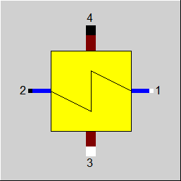 |
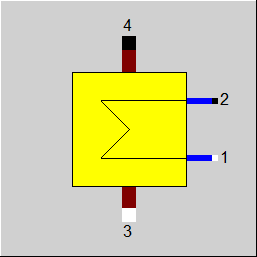
Display Option 1 |
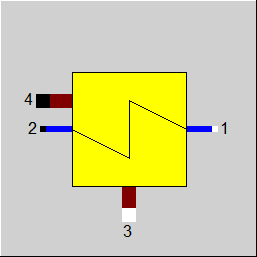 |
Display Option 2 |
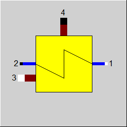 |
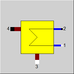
Display Option 3 |
 |
Display Option 4 |
 |
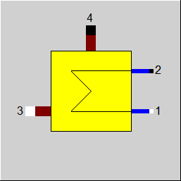
Display Option 5 |
 |
Display Option 6 |
 |
Display Option 7 |
 |
Display Option 8 |
 |
Display Option 9 |
 |
Display Option 10 |
 |
Display Option 11 |
 |
Display Option 12 |
 |
Display Option 13 |
 |
Display Option 14 |
Click here >> Component 73 Demo << to load an example.