
EBSILON®Professional Online Documentation


|
Line connections |
|
|
|
1 |
Cooling medium inlet |
|
|
2 |
Cooling medium outlet |
|
|
3 |
Exhaust steam inlet |
|
|
4 |
Condensate outlet |
|
|
5 |
Auxiliary condensate inlet |
|
|
6 |
Control inlet for KAN or CLTUBE, Design Heat Transfer Capability or Cleanliness factor (as H) |
|
|
7 |
Bypass steam outlet |
|
General User Input Values Characteristic Lines (if FHEI=0) Calculation method according to HEI 6 (if FHEI=1) Calculation method according to HEI 10 (if FHEI=10 or FHEI=-1) Physics Used Displays Example
Contrary to component 10, the amount of the fluid to be condensed and the enthalpy of the fluid have to be defined external to component 7.
In design mode, the incoming fluid pressure (as start or measurement value on line 3) and the upper terminal temperature difference (as specification value DT3S2N see Heat Exchanger General ) have to be provided. Ebsilon then calculates the cooling medium flow rate M1N and the nominal value KAN for k*A (Design Heat Transfer Capability)
In off-design mode, there are several types of calculations, which can be set by specifying FSPEC and FHEI.
Water and salt water can be used as cooling media (even when using the HEI method). Many other cooling media and stream types are also possible. The fluid to be condensed does not have to be water vapour either. Other stream types can also be connected here.
Component 7 is expanded by the HEI 10 method. The previous HEI implementation is renamed to “HEI 6“.
The expansion relates to the calculation of the heat transfer (k and k*A respectively) as well as of the primary pressure drop.
Besides “HEI 6“ and “HEI 10“ it is possible to implement other HEI versions (FHEI = “user-defined“) via user-defined
specification matrices (see below)
First, a differentiation must be made between normal off-design mode and the so-called identification mode. In the normal off-design mode, it is assumed that the performance of the component (i.e. k*A as a function of other influencing parameters) is known and is either specified as a characteristic line, as an adaptation polynomial, or is given by a calculation method known as "Heat Exchange Institute" method. The pressure is calculated in such a way that complete condensation occurs.
In identification mode the measured exhaust pressure is used to identify the component at the particular load point, i.e. to calculate k*A. If the "Heat Exchange Institute" method is chosen, the cleanliness factor of the condenser tubes will be calculated in identification mode.
Irrespective of these different calculation modes, there are also alternatives for specifying the properties of the coolant: if the cooling water flow rate is specified, then Ebsilon calculates the cooling water outlet temperature. In case the cooling water outlet temperature is specified, Ebsilon then calculates the cooling water flow rate. The cooling water flow rate can either be specified as a start value or measurement value on line 1, or it can be assumed as fixed and specified by the specification value M1N. The flag FSPECD allows for the following design options:
As the amount of heat to be transferred is fixed due to the specification of the steam parameters, in the first three cases the cooling water mass flow and in the latter case the outlet temperature of the cooling water is calculated.
Sub Cooling of the condensate is not included. However, it can be modelled by using an after-cooler (component 27). Heat losses to the surroundings can be set with a loss factor..
As, in practice, the condenser pressure is limited not only by the cooling water parameters but also by the evacuating system, specifying a minimum condenser pressure makes sense. This can be effected with the help of the flag FP3MIN, optionally
As an alternative to the adaptation polynomial, an EbsScript function in the specification field EADAPT can be used (see Kernel expressions, chapter 3.2).
When using the HEI method, a validation of the specification value for tube cleanliness (parameter CLTUBE) is possible.
For more information on general notes applicable to most common heat exchangers, see Heat Exchanger General Equations, and a comparison of heat exchanger types in EBSILON can be found in the chapter Heat Exchanger General Components.
Flag FSPECPD:
In Release 13 it is possible specify the design pressure (and also the start value for the internal iteration in off-design) in the component as specification value P3N.
The specification is controlled via the flag FSPECPD.
Flag FDQLR
It is possible, you can use the FDQLR flag to define how DQLR (factor for modeling heat losses) should be interpreted.
External Specification of the Pressure of the Auxiliary Condensate
Since the auxiliary condensate is at the same pressure level as the condensate, it is necessary during modeling to install a control valve or a condensate valve on the auxiliary condensate line in to decrease the pressure to the condenser level.
To simplify the modeling, there is now a mode “P5 given externally“ that can be set by means of the flag FP5. This mode allows to connect a line with a higher pressure on
Pin 5. Within the component, the auxiliary condensate is then reduced to the condenser pressure. The result is the same as with an external control valve.
This mode is the default setting for newly inserted components. For existing models, FP5 is set to “P5=P3“.
Bypass mode
The condenser also contains a flag FFU that allows to turn off the component. While in the case of other heat exchangers “turning off“ means that no heat is transferred, this is not that easily possible for the condenser as here a certain steam quantity is injected that cannot be condensed without heat dissipation. An off-state condenser therefore requires an additional outlet for the uncondensed steam (bypass steam). For this reason, a Pin 7 has been added to the condenser for the bypass steam.
For FFU=0 (“off“) the entire incoming steam is then output unchanged (without pressure and heat loss) via this bypass. The condensate quantity is 0. There is no heat injection on the cold side. The pressure drop, however, is considered. Designing the condenser in bypass operation is not possible, and nor is specifying the cooling water outlet temperature (FSPEC=1). In bypass operation, the condenser pressure is not calculated by the condenser but has to be given externally. The specification can be effected on the bypass line, the steam feed line or the condensate line.
Identification mode
A flag FIDENT for activating the identification mode has been implemented in analogy to other components (obsolete: there was a common flag FSPEC, with which both the identification mode (P3 specification) and the cooling water specification was controlled).
The flag FIDENT has the setting:
For the cooling water specification there is a flag FSPECM with the following settings:
To prevent the behaviour of existing models from changing, the flag FSPEC can still be used. In this case, the settings for FIDENT and FSPECM are ignored.
Logic inlet (Connection point 6) for controlling component properties
(see also : Editing components --> Ports)
To make component properties like efficiencies or heat transfer coefficients (variation quantity) accessible from the outside (for control or reconciliation) it is possible to place the respective value on an auxiliary line as an indexed measured value (specification value FIND). In the component, the same index must then be entered as specification value IPS.
It is also possible to place this value on a logic line that is directly connected to the component (please see FVALKA=2, Variation variable: KAN, Dimension: Enthalpy).
The advantage is that the allocation is graphically visible, and errors (e.g. when copying) are thus avoided.
Treatment of mixtures
As it is also possible to select mixtures (in the Refprop library) when using Component 7 with a line of the type “Two-phase fluid“, Component 7 has been upgraded to treat mixtures correctly. Previously, this feature was only available in Component 107 (Steam turbine condenser for binary mixtures).
As this has made Component 107 redundant, it has been labeled “obsolete“. For reasons of compatibility, of course, it will remain available, so that old models can still be calculated with component 107. Possible future expansions, however, will only be implemented in Component 7, therefore the use of Component 7 is recommended.
Please note for the case of a superheated hot fluid:
This component assumes that the fluid to be condensed does not need to be desuperheated any more and that the impact of the desuperheating on the temperature conditions can be neglected respectively. In the case of admission of a superheated fluid, the energy balance continues to be treated correctly. However, the dew point temperature is used as the temperature relevant for Fourier’s law.
Specifying a negative terminal temperature difference is possible, but then KAN cannot be calculated correctly any more. A warning will be output in this case. If the negative terminal temperature difference is so high that the second law of thermodynamics would be violated, an error message will be output.
In order to achieve a more precise modeling of the condensation of a superheated fluid, the desuperheater has been upgraded for the use of binary mixtures (see Component 43).
Universal fluid
It is possible to use the line type Universal fluid for the fluid to be condensed too. Then, however, an admixture of auxiliary condensate is only possible if it conforms with the fluid to be condensed in terms of composition and used libraries.
Note: A thermo liquid or flue gas can be used as cooling agent for the steam turbine condenser as well.
Performance factor RPFHX
The quotient from the current value for k*A (result value KA) and the k*A expected in the respective load point due to the component physics and characteristic lines respectively (result value KACL) serves to assess the condition of a heat exchanger.
The quotient KA / KACL is displayed as a result value RPFHX.
Component 7 also allows to model the turbine condenser in the transient case. The flag FINST can be used for this purpose. A thermodynamic equilibrium between the liquid and the gaseous phase in the condensate hot well is assumed.
The transient calculation requires the specification of the geometric details of the heat exchanger. The information on the geometry of the pipes already exists for the HEI method. In addition, the transient modeling requires the geometric details on the shell. The fluid volume, wall storage mass, and exchange surface area between wall and fluid are calculated from the geometric details. The properties of the wall material like density, thermal conductivity, and heat capacity can either be specified from the stored library (flags FMTUBE, FMSHELL) or by the user.
The heat exchange between the fluid and the pipe wall / shell wall and the temperature development in the walls over time respectively are also considered. For this purpose, the numerical and analytical algorithm from Component 126 is used. The combined analytic and numeric method like in comp. 119 is used for the computation of the heat exchanger wall temperature.
For the calculation of the convective heat transfer coefficients (ALPH12, ALPH34), the user can choose between the formulae available in the VDI Heat Atlas and own specifications, also e.g. in the form of a user function (EALPH12, EALPH34).
Having the convective heat transfer coefficients (ALPH12, ALPH34) and the heat conductivity of the tube material (LAMBDA) the value of the overall heat transfer coefficient Ktheo can be computed as
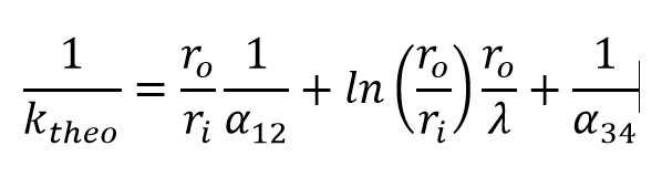
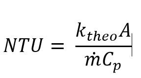
With ro, ri being the outer and the inner tube radius respectively. From the overall heat transfer coefficient Ktheo, the heat transfer area A and the heat capacity flow W computed as the product of the mass flow m times heat capacity value CP the value of the NTU can be computed as
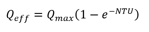
Assuming the stirrer vessel model (VDI Heat Atlas, Edition 11, Chapter C1) for the condenser and applying the NTU-effectiveness method one can compute the heat transferred in the condenser as
To finally apply the Heat Exchangers Equation (5) the calculation of the heat transfer must be corrected by means of a NTU-effectiveness correction factor CORCF (value < 1) and the cleanliness factor CLTUBE as

The factor CORCF is determined in the design calculation as
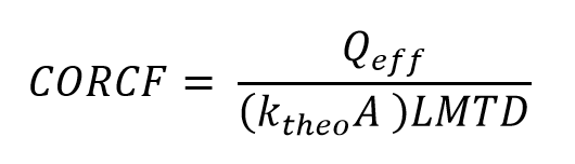
and saved as nominal value CORCFN for the off-design calculation.
For the steady-state solution of the heat exchange, Component 7 allows to choose between the analytical and the numerical solution (flag FALG). In the case of the numerical solution, the result depends on the number of points in flow direction (NFLOW).
The transient mass balance considers a change of the filling level of the condensate hot well during the time step. For the mass balance, the user can decide between the specification of the filling level or of the mass flow M4 by means of the flag FSPIN. The calculated filling level is output as the volume fraction of the liquid phase of the volume between the values of VMIN and VMAX to Pin 6 as mass flow M6.
The temperatures in the outer wall and inner wall and in both fluids are stored in the matrices MXTSTO and RXTSTO. The distribution of the values in the walls and in the fluids is stored in both matrices (default matrix MXTSTO for time step t-1 and result matrix RXTSTO for time step t).
Structure of the matrices see matrices of component 7.
The division in Y-direction in the matrix corresponds to the number NFLOW (confusing, actually the flow direction is the X-direction). Due to the fact that in BT 7 only the reduced model is used (no 2-D grid with Crank Nicolson), there is only one cell in wall normal direction (corresponds to X-direction in the matrix). Therefore, there are exactly
four cells in X direction: Fluid12, Bridge wall (tube wall), Fluid34, Outer wall (shell).
| FINST |
Transient mode: 0: Transient solution (time series or single calculation) 1: Always steady state solution |
|
FFU |
Flag Component On / Component Off =0: Off (hot side bypass, cold side with pressure loss) |
|
FIDENT |
Component identification =0: No Identification |
|
FSPECD |
Specification (for design) =0: use DT3S2N =1: use DT21N =2: T2 externally specified =3: M1 externally specified |
|
DT3S2N |
Upper terminal temperature difference (nominal) T3s-T2 |
|
DT21N |
Cooling medium temperature rise (nominal) |
|
FSPECPD |
Design specification for vapour pressure =0: Design vapour pressure given by specification value P3N =1: Design vapour pressure given externally =-1: Design vapour pressure given externally (in off-design as start value) |
|
P3N |
Steam pressure (nominal) |
|
FSPECM |
Off-design method for cooling water =0: M1=M1N (constant), T2 calculated and P3 calculated (k*A used) |
|
FDP12 |
Cold side pressure drop calculation =0: DP12N (can also be combined with FHEI<>0) =1: Using HEI-method (can also be combined with FHEI=0) |
|
DP12N |
Cold side pressure drop line 1 to 2 (nominal) |
|
DP34N |
Hot side pressure drop line 3 to 4 (nominal) |
| FDPNUM |
Pressure loss handling in the numerical solution =0: Using the average fluid pressure between inlet and outlet |
|
FP5 |
Throttling of secondary condensate =0: No throttling (P5=P3) |
|
FP3MIN |
Minimal condenser pressure definition =0: Definition specification value (P3MIN) |
|
P3MIN |
Minimal condenser pressure |
|
EP3MIN |
Adaptation function for minimal condenser pressure |
|
TOL |
Precision of the energy balance |
|
FDQLR |
Heat loss handling =0: Constant (DQLR*QN in all load cases) |
|
DQLR |
Heat loss to the environment by radiation |
|
FHEI |
Flag for calculation mode "Characteristic line or adaptation polynomial" or according to the "Heat Exchange Institute" =0: No, calculation with specified characteristic line or with adaptation polynomial |
|
FMODE |
Flag for calculation mode Design/Off-design =0: global |
|
FFLOW |
Direction of flow (at present not used) |
|
FSPEC (deprecated) |
Flag for the setting, which parameters are specified and which have to be calculated (concerns only off-design) Normal calculation modes (characteristic line or adaptation polynomial / adaptation function is used): =0: not specified, M1=M1N, T2 and P3 calculated (using k*A) Identification modes (characteristic line and adaptation polynomial are ignored, k*A is calculated from measurement values): =3: T2 and P3 given, M1 calculated, identification of k*A or cleanliness factor CLTUBE (HEI) This flag is ignored in the design mode. The mode FSPEC=6 offers a better transfer of uncertainties ("error propagation") in validation mode by consideration of additional partial derivatives in the system of equations. Especially, a partial derivate with respect to KAN is integrated if KAN is given externally on a logical pipe via a pseudo measurement point. |
|
FADAPT |
Flag for adaptation polynomial / adaptation function =0: Off The specified minimum pressure (P3MIN) is also adhered to in the mode FADAPT=3 and -3 respectively. |
|
EADAPT |
Adaptation function (input) |
|
FVALKA |
Validation of k*A =0: KAN used without validation |
|
FTUBGEOM |
Tube geometry specification (HEI) =0: DTUBEIN and DTUBEOU |
|
FTUBMAT |
Tube material, selection from list (HEI) 0: CuZn28Sn |
|
FTUBMAT10 |
Tube material, selection from list (HEI) 0: Cu Fe 194 |
|
NTUBE |
Total number of tubes (HEI) |
|
ATUBE |
Total outer surface of tubes (HEI) |
|
DWALL |
Tube wall thickness (HEI) |
|
BWG |
Dimensionless specification of the tube wall thickness (wall gauge) in BWG (HEI) |
|
DTUBEIN |
Tube inner diameter (HEI) |
|
DTUBEOU |
Tube outer diameter (HEI) |
|
NPASS |
Number of water passes (HEI) |
|
TUBEVEL |
Averaged flow velocity in the tube HEI, Design only) |
|
TUBELEN |
Tube length per pass (if FDP12=1) |
|
CLTUBE |
Cleanliness factor (FHEI) |
|
IPS |
Index for pseudo measurement point |
|
KAN |
k*A (nominal) , Design Heat Transfer Capability |
|
M1N |
Primary stream mass flow (nominal) |
|
M3N |
Secondary stream mass flow (nominal) |
|
QN |
Generated quantity of heat at nominal load (nominal) |
|
AN |
Total surface area (nominal, if FHEI=10 or FHEI=-1) |
|
VM12N |
Primary averaged volume flow (if FHEI<>0) |
| CORCFN | NTU-Effectiveness correction factor (re-computed in design only) |
| FALG |
Heat exchange calculation algorithm (steady state solution) 0: analytic 1: numeric |
| FBUNDL |
Tube bundle specification =0: Use NTUBE, NPASS and ATUBE |
| FSURF |
Surface area treatment (Design only) 0: use given or computed ATUBE, compute CLTUBE 1: use CLTUBE, compute AN |
| FVEL |
Tube velocity treatment =0: UW computed from tube geometry and current volume flow |
| FINIT |
Flag: Initializing state =0: Global, which is controlled via global variable "Transient mode" under Model Options =1: First run -> Initializing while calculating steady state values |
| SHEIG | Shell height |
| SLENG | Shell length |
| SWIDT | Shell width |
| SWALLT | Shell wall thickness |
| THISO | Thickness of insulation |
| FMTUBE |
Steel grade for the tubes see Material Properties of Steel =-1 : Properties calculated by kernel expression ERHOT, ELAMT, ECPT |
| ERHOT | Function for tube material density |
| ELAMT | Function for tube material heat conductivity |
| ECPT | Function for tube material heat capacity |
| FMSHELL |
Steel grade for the shell see Material Properties of Steel =-1 : Properties calculated by kernel expression ERHOS, ELAMS, ECPS |
| ERHOS | Function for shell material density |
| ELAMS | Function for shell material heat conductivity |
| ECPS | Function for shell material heat capacity |
| LAMISO | Thermal conductivity insulation |
| FALPH12 |
Determination of alpha fluid12 to wall 0: Using internal formulas from VDI Wärmeatlas Edition 11 Chapter G1 1: from constant value AL12N 2: from kernel expression EALPH12 |
| AL12N | Cold side convective heat transfer coefficient (nom.) |
| EALPH12 | Function for ALPH12 |
| FALPH34 |
Determination of alpha fluid34 to wall 0: Using internal formulas from VDI Wärmeatlas Edition 11 Chapter J1 1: from constant value AL34N 2: from kernel expression EALPH34 |
| AL34N | Hot side convective heat transfer coefficient (nom.) |
| EALPH34 | Function for ALPH34 |
| FALPHO |
Determination of alpha outside 0: from specification value ALPHO 1: from function EALPHO |
| ALPHO | Outer heat transfer coefficient (to ambient) |
| EALPHO | Function for alpha outside |
| FSPIN |
Transient balance calculation mode 0: Liquid level given, mass flows computed 1: Mass flows given, liquid level computed |
| VF | Liquid volume fraction (liquid level) at the end of the time step |
| VMIN | Volume at liquid volume fraction 0 |
| VMAX | Volume at liquid volume fraction 1 |
| FLVCALC |
Liquid volume calculation mode 0: linear between VMIN and VMAX 1: Using ELV |
| ELV | Function for the liquid volume computation |
| NFLOW | Number of points in flow direction (max. 100) |
| FNUMSC |
Numeric scheme 0: Upwind (highest stability) 1: Central differences (high accuracy) |
| TMIN | Lower limit for storage temperature |
| TMAX | Upper limit for storage temperature |
| FSTAMB |
Definition of ambient temperature 0: by specification value TAMB 1: defined by reference temperature (comp. 46) |
| TAMB | Ambient temperature |
The parameters marked in blue are reference parameters for off-design, which are calculated by Ebsilon in the design mode. The actual off-design values refer to these parameters in the equations used .
Generally, all inputs that are visible are required. But, often default values are provided.
For more information on colour of the input fields and their descriptions see Edit Component\Specification values
For more information on design vs. off-design and nominal values see General\Accept Nominal values
KOHEI The uncorrected heat transfer coefficient (k-value) according to the HEI method
There are two characteristic lines, which describe the effect of the primary mass flow or of the secondary mass flow respectively on k*A.
The complete correction factor for k*A results from the multiplication of both the influencing factors.
1st Characteristic line CKAM1 FK1 = f (M1/M1N)
2nd Characteristic line CKAM3 FK2 = f (M3/M3N)
Total: (k*A) / KAN = FK1 * FK2
These two cases have to be distinguished:
1. One dimensional state control
This case is characterized by the fact, that there is one M3 assigned to each M1.
In this case you do not need to use the second characteristic line (CKAM3) - thus all values of CKAM3 or FK2 resp. have to be set to 1.0 .
2. More complex states
Different values of M3 are assigned to one M1.
Here you have to use both characteristic lines (CKAM1 und CKAM3).
|
Characteristic line 1: (k*A)-Characteristic line CKAM1: (k*A)1/(k*A)N = f (M1/M1N) |
|
X-Axis 1 M1/M1N 1st point |
|
Characteristic line 2: (k*A)-Characteristic line CKAM3: (k*A)2/(k*A)N = f (M3/M3N) |
|
X-Axis 1 M3/M3N 1st point |
MXHTCOEFF : Heat transfer coefficient (k-value) depending on the flow velocity in the tube and on the tube diameter according to HEI 10
MXTCORR : Correction factor for the heat transfer coefficient depending on the cooling water inlet temperature according to HEI 10
MSMCORR: Correction factor for the heat transfer coefficient depending on the tube material and gauge according to HEI 10
MXHTCOEFFUD: Heat transfer coefficient (k-value) depending on the flow velocity in the tube and on the tube diameter – user-defined
MXTCORRUD: Correction factor for the heat transfer coefficient depending on the cooling water inlet temperature – user-defined
MSMCORRUD: Correction factor for the heat transfer coefficient depending on the tube material and gauge – user-defined
The calculation of KA is based on the method of the "Heat Exchange Institute", which is described in the "VDI Energietechnischen Arbeitsmappe 2000, Chapter 8.2".
|
Calculation of KA (Heat Transfer Capability): Calculation of flow velocity of the cooling water: Calculation of specific density of the cooling water from the specific volume: Calculation of the specific heat of the cooling water:
|
The calculation of KA is based on the method of the "Heat Exchange Institute", which is described in the "HEI Steam Surface Condensers 10th Edition Chapter 4 Condenser Performance"
|
Calculation of KA (Heat Transfer Capability):
The base value of k, K0HEI, is determined from the look-up matrix MXHTCOEFF (FHEI=10) or MXHTCOEFFUD (FHEI=-1) depending on the tube diameter and the flow velocity: The correction factor for the cooling water temperature is determined from the look-up matrix MXTCORR (FHEI=10) or MXTCORRUD (FHEI=-1): |
|
Design case (Simulation flag: GLOBAL= design case and FMODE = GLOBAL) |
||
|
|
P2 = P1 - DP12N P4 = P3 - DP3N P5 = P3 M2 = M1 T3S = fsat (P3) T4S = fsat(P4) DTL = T4 - T1 KAN = DQ/LMTD if FHEI<1, then {> Calculation of the cleanliness factor CLTUBE according to the method of the "Heat Exchange Institute" by specifying KA } |
|
|
Off-design case (Simulation flag: GLOBAL = off-design or FMODE = local off-design) |
||
|
F1 = (M1/M1N) ** 2 P2 = P1 - DP12N * F1 F3 = (M3/M3N) ** 2 M2 = M1 If FHEI=0, then { Start ofiteration T4 = fsat(P4) If FSPEC = 0,2, then { H2 = H1 + Q12/M2 If FSPEC = 1, then { T2 from input } DTL = T4 - T1 If FSPEC = 0, then { M2 = M1 = M1N } |
||
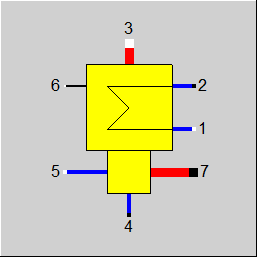 |
Display Option 1 |
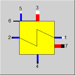 |
Display Option 2 |
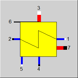 |
Display Option 3 |
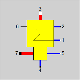 |
Display Option 4 |
Click here >> Component 7 Demo << to load an example.