EBSILON®Professional Online Documentation


Matrices are available as specification matrices and result matrices for some components. The content and meaning of these matrices is described for the respective components.
Specification matrices can be edited on the sheet "Spec matrices". The number of their rows and columns is usually determined by a default value of the component.
Result matrices can be edited with data on the sheet "Result matrices". They can only be used to display the component results generated by a calculation.
Since a matrix is displayed simultaneously as a
either as a heat map or surface plot, it allows a quick visual check of its values.
Specification and result matrices can also be defined for macros of the type "new macro".
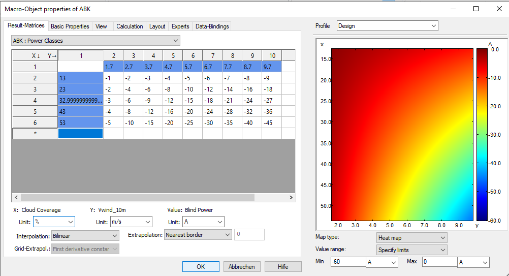
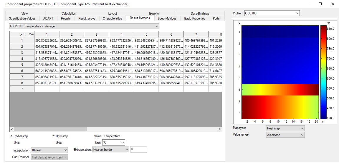
The unit of the values displayed in a matrix is shown in the right of the three "unit" combo boxes and can also be changed here for display.
The X-values (matrix index, row) are displayed in the left table column, the Y-values (matrix index, column) in the upper table row.
In the graphic on the right-hand side, the X and Y axes are each shown with numerical values.
The values from the matrix are assigned to a colour on the colour scale on the far right. The colour used in the graphic representation signals the respective value.
The values are also shown on the Z-axis of the surface plot.
In the heat map, the automatically defined limits can be changed by the user so that a section can be shown enlarged, so to speak, in relation to the Z-axis.
For result matrices, the interpolation settings and extrapolation settings are only used for display, for specification matrices they are also used accordingly during the calculation.
Like default values and the matrix values themselves, these settings can have different values in each profile. The usual inheritance rules apply.
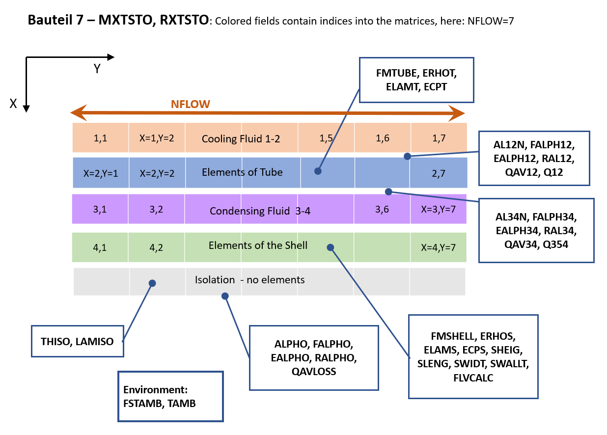
The matrices MXTSTO and RXTSTO are structured as follows. The index Y addresses the columns, the index X the rows.
The assignment of values is determined for all matrices of the component as follows:
The line X = 1 contains the values for the fluid flowing (cooling) through the component between the connections 1 and 2.The line X = 2 contains the values for the pipe.
Line X = 3 contains the values for the fluid flowing (condensing) through the component between connections 3 and 4.
The line X = 4 contains the values for the jacket.
The values in the insulation are not available.
The number of columns Y is given by NFLOW (maximum 100). It is the same for fluids, pipe and jacket.
The number of rows X is 4 (see above).
The number of interpolation points in flow direction is specified with NFLOW (Y direction, maximum 100).
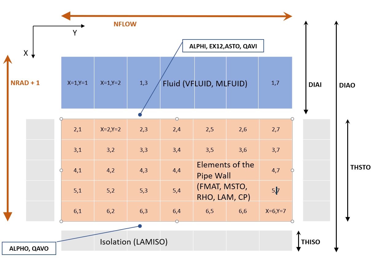
The matrices are structured as follows. The index Y addresses the columns, the index X the rows.
The assignment of values is determined for all matrices of the component as follows:
The line X = 1 contains the values for the fluid flowing through the component between the ports1 and 2.The remaining lines represent the value distribution in the storage wall.
The values in the insulation are not available.
The number of columns Y is specified with NFLOW (maximum 100). It is the same for storage and fluid.
The number of rows X is specified with NRAD (maxmial 30), whereby row 1 is not counted. NRAD is only available when using the Crank-Nicolson method (FALGINST = 1). When using the combined numerical and analytical and methods (FALGINST = 4), NRAD is fixed at 1.
The number of interpolation points in the flow direction is fixed with NFLOW (Y-direction, maximum 100).
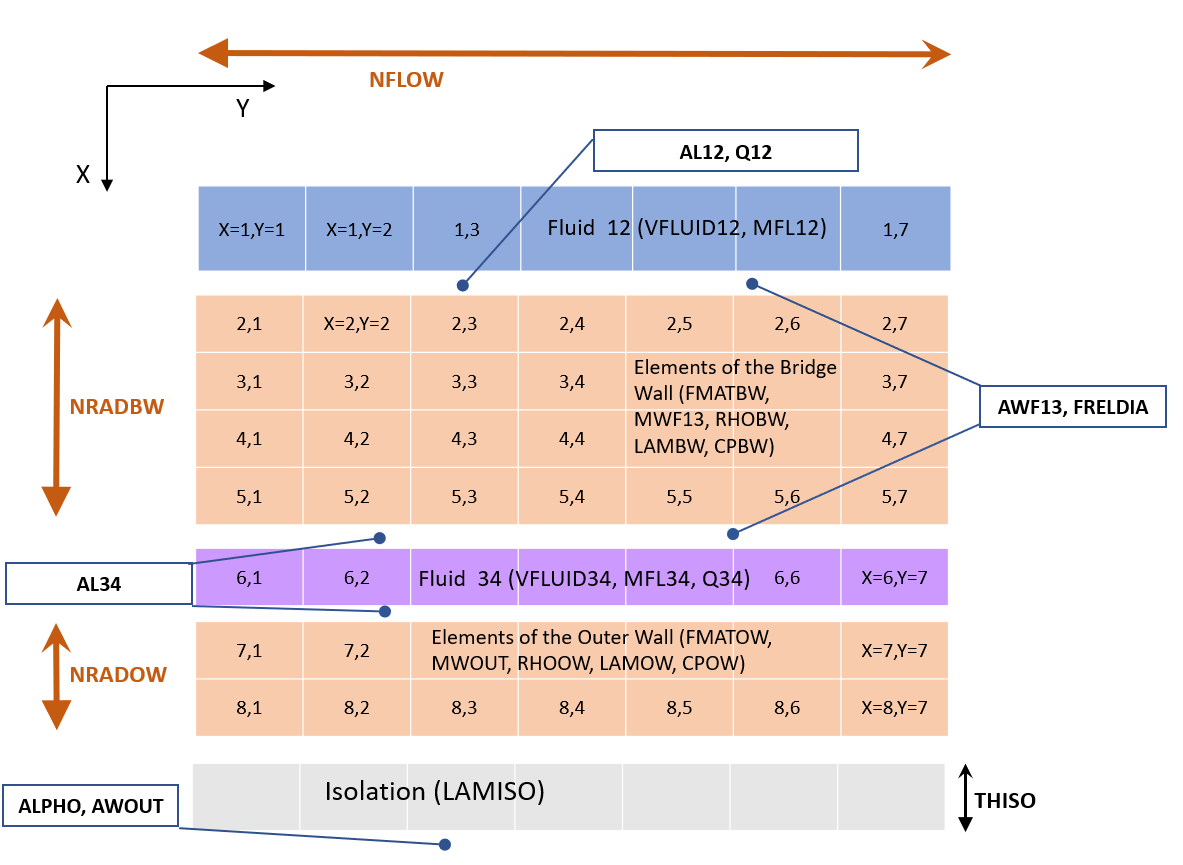
In radial direction (X-direction) the discretisation can be determined independently of each other by two storage areas NRADBW and NRADOW, both fluids have only 1 element each in this direction.
The matrices are structured as follows. The index Y addresses the columns, the index X the rows.
The assignment of values is determined for all matrices of the component as follows:
The line X = 1 contains the values for the fluid flowing through the component between the ports 1 and 2.The lines X = 2 to X = NRADBW+1 contain the values for the bridge wall elements (in the example below (NRADBW=4) lines 2 to 5).
The line X = NRADBW + 2 contains the values for the fluid flowing through the component between the connectors 3 and 4 (in the example below line 6)
The lines X = NRADBW + 3 to NRADBW + NRADOW + 2 contain the values for the elements of the outer wall (in the example below lines 7 and 8).
The values in the insulation are not available.
The number of columns Y is specified with NFLOW.
NRADBW and NRADOW are only available when using the Crank-Nicolson method (FALGINST = 1). When using the combined numerical and analytical and methods (FALGINST = 4), NRADBW and NRADOW are each fixed with 1.
The number of interpolation points in flow direction is fixed with NFLOW (Y-direction, maximum 100), this is then the same for all partial areas of the storage and the fluids.
In radial direction (X-direction) the discretisation of the two storage areas NRADBW and NRADOW can be determined independently of each other, the fluids always have only 1 element in this direction. The total number of Y-elements is a maximum of 30.
The matrices are constructed as described for component 119.
However, NFLOW=1 is fixed, making the matrices practically a one-dimensional array or field. There is therefore no change in the values along the direction of flow of the fluid from port 1 to port 2.
The matrices are structured as follows.
The index Y addresses the columns, the index X the rows.
The assignment of values is determined for all matrices of the component as follows:
The column Y = 1 contains the values for the storage wall.The columns Y = 2 to 5 contain the values for the fluid that can flow through the component between the ports 1 and 2. The columns each contain the same values. One column would also be sufficient.
Lines 1 to NFLOW contain the values for wall and fluid above the height of the reservoir. Line 1 is the top layer in the reservoir, line NFLOW the bottom.
In this way, the graph clearly shows the reservoir content and the narrower wall. Also, the top in the graphic is also the top in reality in the reservoir.
In addition to the properties of the component matrices described above, matrices defined in macros can have
All these matrix data and values can be accessed accessed via EbsScript.