EBSILON®Professional Online Documentation


|
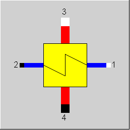
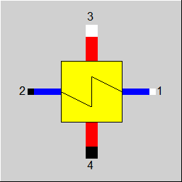
Line connections |
|
|
|
1 |
Primary side inlet (cold stream, inside tubes) |
|
|
2 |
Primary side outlet (cold stream, inside tubes) |
|
|
3 |
Secondary side inlet (hot stream, outside tubes) |
|
|
4 |
Secondary side outlet (hot stream, outside tubes) |
|
General User Input Values Characteristic Lines Physics Used Displays Example
Component 43 models a separate desuperheater for the feed water pre-heating. It is used when the superheated steam is not to be passed directly to a preheater, in which the steam is condensed, but instead is to be desuperheater first. Normally, the desuperheater steam is then led in another feed water preheater further upstream.
The degree of desuperheating does not be complete. In the design case, the specification value DT44SN enables the user to set the degrees fo superheat present at the steam outlet i.e. the temperature difference between the steam coming out and the saturation temperature corresponding to the pressure. For DT44SN = 0, the steam leaving the desuperheater component is not superheated any more (i.e. saturated steam).
The desuperheater can be operated selectively in counter current or concurrent. Upper or lower terminal temperature difference see Heat Exchanger General Notes
The characteristics can be corrected or replaced by an adaption polynomial or a Kernel expression.
There are two identification modes for this component: T2-user (-5) input and T4-user (-4) input. Based on these defaults, k*A is calculated in all load cases. If these methods are used in the design case, then the super heating DT44SN is not an input, but instead the calculated value for DT44S will be copied into DT44SN. In an off-design case, KAN and the characteristic lines are not used.
The degrees of superheat achieved at the outlet is in those cases shown as result value DT44S.
Binary mixtures for the desuperheater:
This component can be used for desuperheating binary mixtures as well.
Here the specification value DT44SN refers to the temperature difference to the dew point temperature of the mixture.
Pressure drop limitations:
As the pressure drop rises quadratically with the mass flow, pressure drops that are significantly too high can quickly arise in the event of a transgression of the nominal mass flow. These will then cause phase transitions and convergence problems (see Heat Exchanger General Notes) .
Design in the Case of Concurrent Flow
In the heat exchanger (Components 43) it is possible to carry out a design via the upper and lower terminal temperature difference also in the case of concurrent flow (FFLOW=1).
If both inlet temperatures are specified, the upper terminal temperature difference can only be determined iteratively. Usually this is no problem. If convergence problems occur in more
complex models, another design mode will have to be used.
Identification mode
In analogy to other components, a flag FIDENT for activating the identification mode has been implemented for the desuperheater too. It has the settings
To prevent the behaviour of existing models from changing, the flag FSPEC can still be used. In this case, the settings for FIDENT are ignored.
Performance factor RPFHX
The quotient from the current value for k*A (result value KA) and the k*A expected in the respective load point due to the component physics and characteristic lines respectively (result value KACL) serves to assess the condition of a heat exchanger.
The quotient KA / KACL is displayed as a result value RPFHX.
For more information on general notes applicable to most common heat exchangers, see Heat Exchanger General Notes
For more information on how this heat exchangers compares to other heat exchangers, see Heat Exchanger General Components
|
FMODE |
Flag for calculation mode design/off-design Like in Parent Profile (Sub Profile option only) Expression =0: GLOBAL =1: local off-design (i.e. always off-design mode, even when a design calculation has been done globally) =2: special local off-design (special case for compatibility with earlier Ebsilon-versions, should not be used in new models, because the results of real off-design calculations are not consistent) = -1: local design |
|
DP12N |
Cold side pressure loss line 1 to 2 (nominal) |
|
DP34N |
Hot side pressure loss line 3 to 4 (nominal) |
|
FIDENT |
Specifications Like in Parent Profile (Sub Profile option only) Expression =0: No Identification |
|
DT44SN |
Super Heating temperature difference (nominal) |
|
TOL |
Tolerance in the energy balance |
|
FFLOW |
Flag for the direction of flow, see Heat Exchanger General Notes Expression =0: counter current flow =1: concurrent flow |
|
FADAPT |
Flag for adaptation polynomial ADAPT/ adaptation function EADAPT Like in Parent Profile (Sub Profile option only) Expression =0: not used and not evaluated =1: Correction for k*A [KA = KAN * char line factor * polynomial] =2: Calculation of k*A [KA = KAN * polynomial] =1000: Not used but ADAPT evaluated as RADAPT (Reduction of the computing time)
= -2: Calculation of k*A [KA = KAN * adaptation function ] = -1000: Not used but EADAPT evaluated as RADAPT (Reduction of the computing time) |
|
EADAPT |
Adaptation function for KA (input) |
|
FFU
|
Switch OF / ON Like in Parent Profile (Sub Profile option only) Expression =0: Heat exchanger off (no heat transfer, but calculated pressure loss =1: Heat exchanger on (active) |
|
FSPEC (deprecated) |
Combined switch (deprecated) Like in Parent Profile (Sub Profile option only) Expression -999: unused (FIDENT used instead) deprecated: =11: T2 and T4 are calculated (in the design mode from DT44SN, in off-design from KAN and the characteristic lines) =-5: T2 is specified (also in off-design), KA is calculated. DT44SN or KAN and the characteristic lines are not used. =-4: T4 is specified (also in off-design), KA is calculated. DT44SN or KAN and the characteristic lines are not used. |
|
KAN |
Heat transfer coefficient * area (nominal) - Design Heat Transfer Capability |
|
M1N |
Cold side mass flow (nominal) |
|
M3N |
Hot side mass flow (nominal) |
The parameters marked in blue are reference quantities for the off-design mode. The actual off-design values refer to these quantities in the equations used.
Generally, all inputs that are visible are required. But, often default values are provided.
For more information on colour of the input fields and their descriptions see Edit Component\Specification values
For more information on design vs. off-design and nominal values see General\Accept Nominal values
1st Correction factor dependent on primary mass flow CKAM1 FK1 = f (M1/M1N)
2nd Correction factor dependent on secondary mass flow CKAM3 FK2 = f (M3/M3N)
(K*A)/(K*A)N = FK1 * FK2
|
Characteristic line 1: Correction factor dependent on primary mass flow CKAM1: (k*A)1/(k*A)N = f (M1/M1N) |
| X-axis 1 M1/M1N 1st point 2 M1/M1N 2nd point . N M1/M1N last point Y-axis 1 (k*A)1/(k*A)N 1st point 2 (k*A)1/(k*A)N 2nd point . N (k*A)1/(k*A)N last point |
|
Characteristic line 2: Correction factor dependent on secondary mass flow CKAM3: (k*A)2/(k*A)N = f (M3/M3N) |
|
X-axis 1 M3/M3N 1st point |
|
Design case (Simulation flag: GLOBAL = design and FMODE = GLOBAL) |
||
|
|
P4 = P3 - DP34N
T4 = T4S + DT44SN H4 = f (P4,T4) M4 = M3 Q4 = M4 * H4 DQ = Q3 -Q4 P2 = P1 - DP12N Q2 = Q1 + DQ M2 = M1 H2 = Q2 / M2 T2 = f (P2,H2) for Fflow = cross-counter flow { DTL = T4 - T1 DTU = T3 - T2 } for Fflow= counter current flow { DTL = T4 T2 DTU = T3 T1 } LMTD = (DTU - DTL)/(ln(DTU) - ln(DTL)) (k*A)*LMTD = M2*H2 - M1*H1 (k*A)*LMTD = M3*H3 - M4*H4 |
|
|
Off-design case (Simulation flag: GLOBAL = off-design or FMODE = local off-design) |
||
|
|
F1 = (M1/M1N) ** 2 at GLOBAL = design: F1=1.0 P2 = P1 - DP12N * F1
FK2 = f (M3/M3N) characteristic line connection 2 for GLOBAL = design: FK2=1.0 (k*A) = (k*F)N * FK1 * FK2 F3 = (M3/M3N) ** 2 at GLOBAL = design: F3=1.0 P4 = P3 - DP34N * F3 M4 = M3 maximum/minimum values for the iteration H2max = f (P2,T3) Q12max = M1 * (H2max - H1) H4min = f (P4,T1) Q34max = Q3 - M4 * H4min for FFLOW= (cross-counterflow/backward flow) { Qmax = min(Q12max,Q34max) } for FFLOW=(counter current) { Estimation for the start of the iteration QA = min(Q12max,Q34max) QM = QA*QA/(Q12max+Q34max) Iteration mark 1 H2 = h1 + QM / M2 T2 = f (P2,H2) T4 = T2 H4 = f (P4,T4) QP = Q3 -M4 * H4 DQ = QM - QP regula falsi method (QM - QMalt) grad = -------------------- (DQ - DQalt) QM = QM - DQ * grad End of the regula falsi method | DQ | DQ = |--------------------| | (QM+QP)*0.5| if DQ < TOL, then end iteration 1 Qmax = QM } Q12 = 0.5* Qmax Iteration mark 2 H4 = (Q3 - Q12)/M4 T4 = f (P4,H4) H2 = H1 + Q12/M2 T2 = f (P2,T2) for FFLOW = counter current flow { DTL = T4 - T1 DTU = T3 - T2 } for FFLOW = concurrent flow { DTL = T4 -T2 DTU = T3 -T1 }
LMTD = (DTU - DTL)/(ln(DTU) - ln(DTL)) QQ = (k*A) * LMTD DQQ = Q12 - QQ regula falsi method(Q12 - Q12alt) grad = ------------------------- (DQQ - DQQalt) Q12 = Q12 - DQQ * grad End of the regula falsi method | DQQ | DQ = |--------------------| |(Q12+QQ)*0.5| if DQ < TOL then end iteration 2 (k*A)*LMTD = M2*H2 - M1*H1 (k*A)*LMTD = M3*H3 - M4*H4 |
|
 |
Display Option 1 |
Click here >> Component 43 Demo << to load an example.