EBSILON®Professional Online Documentation


|
Line connections |
|
|
|
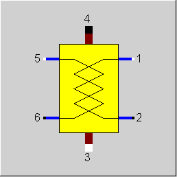
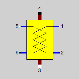
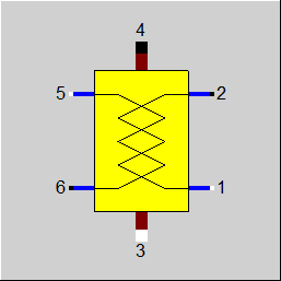
1 |
Primary inlet, cold side (Water/Steam) |
|
|
2 |
Primary outlet, cold side (Water/Steam) |
|
|
3 |
Secondary inlet, hot side (Flue gas) |
|
|
4 |
Secondary outlet, hot side (Flue gas) |
|
|
5 |
Primary inlet, cold side (Water/Steam) |
|
|
6 |
Primary outlet, cold side (Water/Steam) |
|
General User Input Values Characteristic Lines Physics Used Displays Example
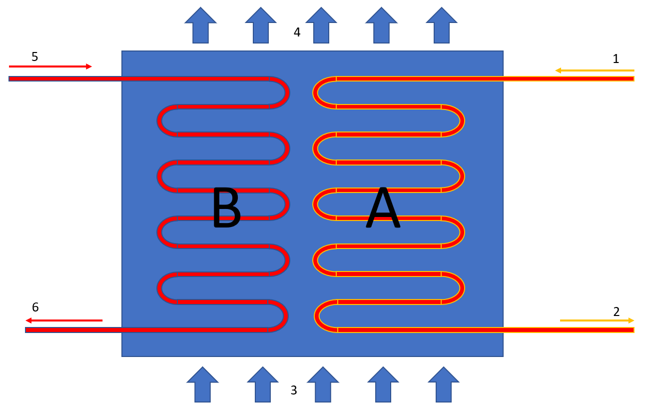
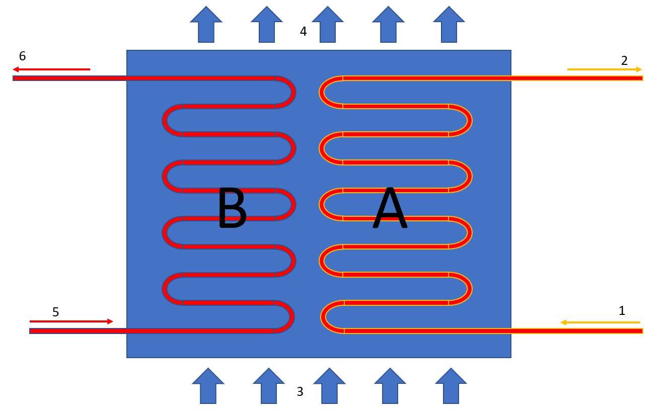
Component 62 is a combination of two heat exchanger components connected in parallel on the flue gas side.
Component 62 is a multi-purpose component that can be inserted as economizer, evaporator or super heater (any combination of two is possible as well).
It differs from component 26 in the method of calculation of the (k*A)-values in the off-design mode. Component 26 takes a characteristic line as a basis, whereas component 62 uses the relationships of individual heat transfer coefficient for both sides of the tubes. The nominal values for the convective heat transfer coefficients and the exponents for the off-design scaling must be specified here.
The default values available for the user inputs when inserting the component are suitable for water as the primary medium and flue gas as the secondary medium. An adjustment of the values is needed when using other fluids.
In the design case, the user must specify, in what way (as Economizer, Evaporator or Super Heater or also as general heat-exchanger) the two lines of the component are used. Moreover, the terminal temperature difference (upper and lower : (see Heat Exchanger General Notes ) )or the flue gas inlet temperature in the design case is also to be specified.
Alternatively, it is also possible to avoid the internal terminal temperature differences or the temperature specifications and instead specify three of the four temperatures at the inlets and the outlets externally. In each case, the result of the design calculation is the nominal value for k*A, KAN.
In the off-design calculation mode, an off-design k*A is calculated from this KAN by using the physical laws. There was only one adaptation polynomial that was then used for the KA on both legs. As of Release 10 separate kernel expressions can be used for each heat transfer. The control is also carried out via the flag FADAPT :
Here the flag FADAPT applies to both heat transfers. If a kernel expression is to be used only for one heat transfer, a function value of 1 is to be returned for the other one (this is also the default function). There is now a result value KAKAN (KAKAN / KAKANB) for the related KA value (KA12N / KA56N) for each line section.
Optionally, an adaption polynomial (as supplement or as replacement) can also be specified for the off-design scaling. A defined adaption polynomial is then valid for both the lines.
Alternatively, there is also an identification mode: specification of T2 and T6. In this mode, in the off-design case, one does not work with the KAN and the corresponding scaling laws, but instead calculates k*A in such a way that the result is the desired temperature. In the identification mode, it is not necessary to differentiate between an Economizer, Evaporator, Super Heater or general heat-exchanger. The two lines can only be identified simultaneously.
The component can be deactivated (both lines at the same time) with the switch FFU. In that case, heat is no longer exchanged, but pressure losses are still taken into account.
Radiation losses DQLR can defined by means of a loss factor.
Pressure drop limitations in off-design :
(Extras --> Model Options--> Calculation -->Relative pressure-drop maximum) :
As the pressure drop rises quadratically with the mass flow, pressure drops that are significantly too high can quickly arise in the event of a transgression of the nominal mass flow. These will then cause phase transitions and convergence problems. For this reason, pressure drop limitations have been installed.
Constant pressure loss (FVOL=2):
For these components, it is possible to specify a constant pressure drop. This is especially helpful when the pressure drop is known for a certain part load point (from measurement, e.g.) or you want to use your own formula for the pressure drop.
Handling of pinch point violations
Up to release 10.0, a pinchpoint violation was only determined subsequently in partial load, i.e. KA was calculated for the respective load case and from this the transferred heat quantity and then it was checked whether this heat quantity can be transferred at all at the correct temperature level. Since in the case of evaporation or condensation the temperature remains constant despite heat input or heat removal, there are cases where heat transfer is not physically possible despite the overall balance being correct. In this case, an error message was issued in Ebsilon.
The calculation has now been changed in such a way that the transferred heat quantity is reduced as far as it is still physically possible, with the minimum pinch point can be set in a default value PINPMIN. This results in a correspondingly reduced KA.
The user is informed of this by a warning message ("KA reduced to avoid pinchpoint violation") and can then adjust the part-load characteristic curve or the part-load exponent for KA accordingly so that the warning no longer occurs. The advantage, however, is that one gets a physically possible result in any case.
Furthermore, at the end of the calculation there is a check if there is a pinch point violation due to curved course of Q(T) (caused by significant changes of cp depending on the temperature). This can be verified by dividing the heat exchanger into individual sections.
This case can occur, for example, when on the hot side the cp at the inlet is significantly smaller than at the outlet (for example, steam that has a cp of about 2 kJ/kgK at high superheat, but more than 5 just above the boiling line). This means that this steam provides more heat at a lower temperature level than at a high one. At appropriately low degrees, this can be a limitation on the amount of heat transfer that is possible.
The QT diagrams take into account the non-linearity (curvature of the curves) in areas without phase change.
Adjustable tolerance limit for the evaporation in an economizer
A warning message was issued when the steam content at the outlet of an economizer increased 2.5%, and an error message was issued when the steam content increased 5%. As desired by customers, this limit is adjustable using a specification value TOLXECO.
For X>TOLXECO, a warning message is issued, for X>2*TOLXECO an error message is issued. Note: Nevertheless, the calculation does not distinguish between economizer and evaporation zone but uses a the same k value for both zones.
Specification of the surface area for designing heat exchangers
Usually, heat exchangers are designed in Ebsilon by specifying the terminal temperature differences or temperatures to be achieved. In an iterative process, the transferred amount of heat and the product of heat transfer coefficient and surface area (k*A) characteristic for the heat exchanger are calculated from this. Its nominal value KAN then serves to calculate the temperatures in off-design calculations. It is not necessary to know the individual values k and A here.
In the case of the components ECO/Evaporator/Superheater (exponents, Component 61), Duplex heat exchanger (Component 62), and Evaporator with steam drum (Component 70), however, the off-design behaviour is defined by exponents of heat transfer coefficients AL12 and AL56. As k can be calculated from it, the heat exchanger surface area A is available as well.
This has been used to implement a design calculation via the specification of the surface area. It is, however, essential to correctly specify the nominal values for the heat transfer coefficients AL12N and AL56N, which had only an effect on the partial load behaviour before to implementation of AN (area).
The specified surface areas A12N / A56N are only used for the design calculation to determine KAN from it. In the off-design calculation KAN is then used for the calculation.
The flag FSPEC (deprecated) has been divided into three flags:
Note:
When loading a model that was created with Release 11 (or older), the corresponding values for FTYPHX, FSPECD, and FIDENT are determined from the value of the flag FSPEC, and FSPEC is set to “void” (-999). The model then calculates with these as before. If required, however, the flag FSPEC can still be used as well. This is necessary so that the existing EbsScripts in which a switchover of FSPEC into an identification mode is carried out will continue working. If FSPEC is not “empty” (-999) but has a value of -4 or -5 (the old values for the identification modes), the new flag FIDENT will be ignored, and the component will behave according to the setting of FSPEC (this is indicated in a comment).
For this component there was an FSPEC (deprecated ) with an according amount of variants for each leg (1-2 and 5-6). These have become FTYPHX and FSPECD for each leg, but only one FIDENT, as also the identification mode was only possible for both legs at the same time (an error message was generated in the case of different settings).
Different FTYPHX are no problem. Legs 1-2 and 5-6 are spatially divided pipes, so it is possible to heat liquid water in the one leg and steam in the other one.
The design mode FSPECD is more problematic. In Release 11 all combinations could be selected for it, but some of them always led to error messages. In the design it is necessary to define which heat quantity is transferred to leg 1-2 and which heat quantity to leg 5-6. If FSPECD = 1, 2, 5, or 9 for both legs, the heat quantities can be determined directly.
The distribution of the heat quantity resulted from the start value of the internal iteration (where each leg receives 50 percent of the flue gas quantity). Of course, each other internal distribution would fulfill the specification just as well. In order to prevent faulty specifications in advance, when selecting FSPECD12 = 3 or 4 the flag FSPECD56 is hidden, and the values from leg 1-2 are also used for leg 5-6. Additionally, a warning is issued that the distribution in not unique.
To remove ambiguity, the terms “primary side” and “secondary side” respectively have been replaced by “cold side” and “warm side” in the input screens. The cold side is the flow from Pin 1 to Pin 2 that is heated. The warm side is the flow from Pin 3 to Pin 4 that gives off the heat.
Design in the Case of Concurrent Flow (as of Release 12) see Heat Exchanger General Notes
In the heat exchanger (Components 62) it is possible to carry out a design via the upper and lower terminal temperature difference also in the case of concurrent flow (FFLOW=1).
If both inlet temperatures are specified, the upper terminal temperature difference can only be determined iteratively. Usually this is no problem. If convergence problems occur in more complex models, another design mode will have to be used.
For an evaporator, the outlet temperature is defined by the pressure. Thus in this case one degree of freedom less is available. Therefore specifying the upper terminal temperature difference (in counter current flow) was not possible for the evaporator.
Only for component 61 is now possible also in the case of an evaporator and the specification value FTYPHX =Evaporator without super heating (5) can be set the upper terminal temperature difference (in counter current flow) or lower terminal temperature difference (in concurrent flow) for the design.
Flag FDQLR
It is possible, you can use the FDQLR flag to define how DQLR (factor for modeling heat losses) should be interpreted.
Specific heat capacity : CP12 / CP34
The mean specific heat capacity is now displayed as result value on the cold side (CP12) and on the hot side (CP34).
The mean specific heat capacity results from the quotient of the enthalpy difference and the temperature difference.
If no temperature difference is present (e.g. in the two-phase range or when the heat exchanger is shut off), however, it is not possible to calculate this quotient. In this case, the specific heat capacity at the respective temperature is used, provided that it is defined. Otherwise the result value will remain blank.
For more information on general notes applicable to most common heat exchangers, see Heat Exchanger General Notes
For more information on how this heat exchangers compares to other heat exchangers, see Heat Exchanger General Components
To understand the chosen designations of the specification and result values - countercurrent at the top, co-current at the bottom:
|
FMODE |
Flag for calculation mode Design/Off-design =0: Global =1: local off-design (i.e. always off-design mode, even when a design calculation has been done globally) =2: special local off-design (Special case for compatibility with the earlier Ebsilon-versions, should not be used in new models, because the results of the real off-design calculations are not always consistent) = -1: local design |
|
|
FFU |
Flag On/Off =0: Heat exchanger off (no heat transfer, but pressure losses) =1: Heat exchanger active |
|
|
FTYPHX12 |
Type of heat exchanger stream 1-2 = 0: General heat exchanger |
|
|
FTYPHX56 |
Type of heat exchanger stream 5-6 = 0: General heat exchanger |
|
|
FSPECD12 |
Calculation method in design-case for stream 1-2 or both streams = 1: Specification of the lower terminal temperature difference (=T4-T1) for stream 1-2 given as DTAN |
|
|
FSPECD56 |
Calculation method in design-case for stream 5-6 = 1: Specification of the lower terminal temperature difference (=T4-T5) for stream 5-6 given as DTBN |
|
|
DTAN |
Terminal temperature difference for stream 1-2 (nominal) in the design case Depending upon the value of FSPECD12, the following are to be entered here
For other values of FSPECD12 , the value of DTAN is ignored. |
|
|
DTBN |
Terminal temperature difference for stream 5-6 (nominal) in the design case Depending upon the value of FSPECD56, the following are to be entered here
For other values of FSPECD56, the value of DTBN is ignored. |
|
|
A12N |
Heat transfer area line 12 (nominal) |
|
|
A56N |
Heat transfer area line 56 (nominal) |
|
|
FIDENT |
Component identification (only in off-design) =0: No identification mode |
|
|
FVOL |
Flag for considering the dependency of pressure loss on volume =0: Only depending on mass flow DP/DPN = (M/MN)**2 =1: Depending on mass and volume flow DP/DPN = V/VN*(M/MN)**2 =2: constant pressure drop (no load dependency) |
|
|
FDP12RN |
Pressure loss reference type line 12 =1: (absolute) Calculated by DP12N= DP12RN =2: (relative) Calculated by DP12N=P1N*DP12RN =-1:P2 given from outside |
|
|
DP12RN |
Pressure loss 12 (nominal) [absolute or relative to P1] |
|
|
FDP56RN |
Pressure loss reference type line 56 =1: (absolute) Calculated by DP56N= DP56RN =2: (relative) Calculated by DP56N=P5N*DP56RN =-1:P6 given from outside |
|
|
DP56RN |
Pressure loss 56 (nominal) [absolute or relative to P5] |
|
|
FDP34RN |
Pressure loss reference type line 34 =1: (absolute) Calculated by DP34N= DP34RN =2: (relative) Calculated by DP34N=P3N*DP34RN =-1:P4 given from outside |
|
|
DP34RN |
Pressure loss 34 (nominal) [absolute or relative to P3] |
|
|
FDQLR |
Heat loss handling =0: Constant (DQLR*QN in all load cases) |
|
|
DQLR |
Heat loss (relative) |
|
|
PINPMIN |
Minimum value for the pinch point (KA is reduced automatically if the pinch point would fall below this value) |
|
|
TOL |
Maximum permissible tolerance in energy balance for the internal iteration
|
|
|
TOLXECO |
Tolerance for evaporation in an economizer. If the steam content X at the economizer outlet is > TOLXECO, a warning message is issued. If it is > 2*TOLXECO, an error message is issued. |
|
|
AL12N |
Convective heat transfer coefficient stream 12 (nominal) |
|
|
AL56N |
Convective heat transfer coefficient stream 56 (nominal) |
|
|
AL34N |
Convective heat transfer coefficient stream 34 (nominal) |
|
| DAL34DT | Additional partial load gradient for AL34 - see component 61 The temperature dependency of AL34 can thus be influenced - default value up to release 16: 0.0005 |
|
|
EX12 |
Mass flow exponent of AL12 (Heat transfer coefficient for stream 12) AL12 = AL12N*(M1/M1N**EX12) |
|
|
EX56 |
Mass flow exponent of AL56 (Heat transfer coefficient for stream 56) AL56 = AL56N*(M5/M5N**EX56) |
|
|
EX34 |
Mass flow exponent of AL34 (Heat transfer coefficient for stream 34) AL34 = AL34N*(M3/M3N**EX34)* (1 - (TM34N-TM34)*5E-4/°K) |
|
|
FFLOW12 |
Flag for direction of flow stream 1-2 , see Heat Exchanger General Notes =0: Counter Current flow =1: Concurrent flow =2: Cross flow |
|
|
NROW12 |
Number of rows (for cross flow) of stream 1-2 |
|
|
NPASS12 |
Number of passes (for cross flow) stream 1-2 |
|
|
FARR12 |
Flag for specification of the arrangement of passes 12 =0: Counter Current flow =1: Concurrent flow |
|
|
FFLOW56 |
Flag for direction of flow stream 5-6 =0: Counter Current flow =1: Concurrent flow =2: Cross flow |
|
|
NROW56 |
Number of rows (for cross flow) of line 56 |
|
|
NPASS56 |
Number of passes (for cross flow) of line 56 |
|
|
FARR56 |
Flag for specification of the arrangement of passes 56 =0: Counter Current flow =1: Concurrent flow |
|
|
FADAPT |
Flag for using the adaptation polynomial ADAPT/ adaptation function EKAij =0: Not used and not evaluated =1: Correction for k*A =2: Calculation of k*A =1000: Not used, but ADAPT evaluated as RADAPT (Reduction of the computing time) = -1: Correction for k*A = -2: Calculation of k*A = -1000: Not used, but EADAPT evaluated as RADAPT (Reduction of the computing time) |
|
|
EKA12 |
Function for KA12 |
|
|
EKA56 |
Function for KA56 |
|
|
FSPEC12 (deprecated) |
Combi switch for operation type and temperature definitions for stream 12 (except for the last mode only for the design case) = -999: unused (FSPECD and FIDENT used instead) old values: =41: General heat-exchanger, DTAN= lower terminal temperature difference given =42: General heat-exchanger, DTAN= upper terminal temperature difference given =43: General heat-exchanger, DTAN= T4 given =44: General heat-exchanger, given (T3, T4) and (T1 or T2) =45: General heat-exchanger, given (T1, T2) and (T3 or T4) =49: General heat-exchanger, given AN= area =12: Economizer, DTAN= upper terminal temperature difference given =13: Economizer, DTAN= T4 given =14: Economizer, given (T3, T4) and (T1 or T2) =15: Economizer, given (T1, T2) and (T3 or T4) =19: Economizer, given AN= area =21: Evaporator, DTAN= lower terminal temperature difference given =22: Evaporator, DTAN= upper terminal temperature difference given =23: Evaporator, DTAN= T4 given =24: Evaporator, given (T3, T4) and (T1 or T2) =25: Evaporator, given (T1, T2) and (T3 or T4) =29: Evaporator, given AN= area
=31: Superheated, DTAN= lower terminal temperature difference given =32: Superheated, DTAN= upper terminal temperature difference given =33: Superheated, DTAN= T4 given =34: Superheated, given (T3, T4) and (T1 or T2) =35: Superheated, given (T1, T2) and (T3 or T4) =39: Superheated, given AN= area
=2: General heat-exchanger, DTAN= upper terminal temperature difference given, off-design depending on EX12 only =3: General heat-exchanger, DTAN= T4 given, off-design depending on EX12 only =4: General heat-exchanger, given (T3, T4) and (T1 or T2), off-design depending on EX12 only =5: General heat-exchanger, given (T1, T2) und (T3 or T4), off-design depending on EX12 only =-5: T2 and T6 given (also in off-design). Note: If this method is used in off-design, the mass and energy balances will be observed, but the heat exchanger will be resized. Use this method only when appropriate, such as for data reconciliation. This method could violate the second law of thermodynamics. |
|
|
FSPEC56 (deprecated) |
Combi switch for operation type and temperature definitions at line 56 (except for the last mode only for the design case) = -999: unused (FSPECD and FIDENT used instead) old values: =41: General heat-exchanger, DTBN= lower terminal temperature difference given =42: General heat-exchanger, DTBN= upper terminal temperature difference given =43: General heat-exchanger, DTBN= T4 given =44: General heat-exchanger, given (T3, T4) and (T5 or T6) =45: General heat-exchanger, given (T5, T6) and (T3 or T4) =49: General heat-exchanger, given AN= area =11: Economizer, DTBN= lower terminal temperature difference given =12: Economizer, DTBN= upper terminal temperature difference given =13: Economizer, DTBN= T4 given =14: Economizer, given (T3, T4) and (T5 or T6) =15: Economizer, given (T5, T6) and (T3 or T4) =19: Economizer, given AN= area =21: Evaporator, DTBN= lower terminal temperature difference given =22: Evaporator, DTBN= upper terminal temperature difference given =23: Evaporator, DTBN= T4 given =24: Evaporator, given (T3, T4) and (T5 or T6) =25: Evaporator, given (T5, T6) and (T3 or T4) =29: Evaporator, given AN= area
=31: Super-heater, DTBN= lower terminal temperature difference given =32: Super-heater, DTBN= upper terminal temperature difference given =33: Super-heater, DTBN= T4 given =34: Super-heater, given (T3, T4) and (T5 or T6) =35: Super-heater, given (T5, T6) and (T3 or T4) =39: Super-heater, given AN= area =1: General heat-exchanger, DTAN= lower terminal temperature difference given, off-design depending on EX56 only =2: General heat-exchanger, DTAN= upper terminal temperature difference given, off-design depending on EX56 only =3: General heat-exchanger, DTAN= T4 given, off-design depending on EX56 only =4: General heat-exchanger, given (T3, T4) und (T5 or T6), off-design depending on EX56 only =5: General heat-exchanger, given (T5, T6) und (T3 or T4), off-design depending on EX56 only =-5: T2 and T6 user enters (also in off-design). Note: If this method is used in off-design, the mass and energy balances will be observed, but the heat exchanger will be resized. Use this method only when appropriate, such as for data reconciliation. This method could violate the second law of thermodynamics. |
|
|
KA12N |
Heat transfer coefficient *area line 12 (nominal) - Design Heat Transfer Capability |
|
|
KA56N |
Heat transfer coefficient *area line 56 (nominal) - Design Heat Transfer Capability |
|
|
QN |
Heat exchanger capacity (nominal) =Q34N |
|
|
M1N |
Mass flow cold side, Line12 (nominal) |
|
|
M5N |
Mass flow cold side, Line 56 (nominal) |
|
|
M3N |
Mass flow hot side, Line 34 (nominal) |
|
|
P1N |
Pressure inlet at point 1 (nominal) |
|
|
P5N |
Pressure inlet at point 5 (nominal) |
|
|
P3N |
Pressure inlet at point 3 (nominal) |
|
|
TM34N |
Medium temperature of flue gas temperature (nominal) TM34N=(T3N+T4N)/2 |
|
|
V1N |
Specific volume inlet at point 1 (nominal) |
|
|
V5N |
Specific volume inlet at point 5 (nominal) |
|
|
V3N |
Specific volume inlet at point 3 (nominal) |
The parameters marked in blue are reference quantities for the off-design mode. The actual off-design values refer to these quantities in the equations used.
Generally, all inputs that are visible are required. But, often default values are provided.
For more information on colour of the input fields and their descriptions see Edit Component\Specification values
For more information on design vs. off-design and nominal values see General\Accept Nominal values
FK1 = (M1/M1N)**EX12
FK3 = (M5/M5N)**EX56
TM34 = 0.5*(T3+T4)
FK2 = (1 - 0.0005 * (TM34N-T34N) ) * (M3/M3N)**EX34
if line 12 is a super heater
K12N = 1 / ( 1 / AL12N +1/ AL34N )
K12 = 1 / ( 1 / (AL12N*FK1) + 1 / (AL34N*FK2) )
else
K12N = 1 / ( 1 / AL34N )
K12 = 1 / ( 1 / (AL34N*FK2) )
if line 56 is in superheated state
K56N = 1 / ( 1 / AL56N +1 / AL34N )
K56 = 1 / ( 1 / (AL56N*FK3)+1 / (AL34N*FK2) )
else
K56N = 1 / ( 1 / AL34N )
K56 = 1 / ( 1 / (AL34N*FK2) )
KA12/KA12N = K12/K12N
KA56/KA56N = K56/K56N
|
All Cases |
||
|
|
if FDP12RN=relative, then {DP12N=P1*DP12RN} else {DP12N=DP12RN} if FDP34RN=relative, then {DP34N=P3*DP34RN} else {DP34N=DP34RN} if FDP56RN=relative, then {DP56N=P5*DP56RN} else {DP56N=DP56RN} |
|
Higher iteration loop:
with the aim of distributing the flue gas mass flows on both the primary mass flows so that the outlet temperatures T2 and T6 are identical.
|
All cases |
||
|
|
Starting value
if the 1st iteration step { Mfac = .5 Size = .01, then } else { Mfac = Mfac_1 }
|
|
|
|
||
|
Calculation of the mass flow 12 |
||
|
Design (Simulation flag: GLOBAL = Design and FMODE = Design) |
||
|
|
if the lower terminal temperature difference is given and FFLOW = counter current {
P4 = P3 - DP3N T4 = T1 + DTAN H4A = f(P4,T4) M4 = M3 Q4A = M4 * H4A DQ = (Q3 - Q4A)*(1-DQLR) P2 = P1 - DP12N Q2 = Q1 + DQ M2 = M1 H2 = Q2/M2 T2 = f(P2,H2) DTLO = T4 - T1 (for FFLOW = counter current) DTUP = T3 - T2 (for FFLOW = counter current) LMTD = (DTUP - DTLO)/(ln(DTUP) - ln(DTLO)) KA12N = DQ/LMTD KA12N*LMTD = M2*H2 - M1*H1 KA12N*LMTD = (M3*H3 - M4*H4A)*(1 - DQLR) }
if the upper terminal temperature difference is given and FFLOW = counter current { P2 = P1 - DP12N T2 = T3 - DTAN M2 = M1 H2 = f(P2,T2) Q2 = M2 * H2 DQ = Q2 - Q1 P4 = P3 - DP34N Q4A = Q3 - DQ/(1-DQLR) M4 = M3 H4A = Q4A/M4 T4 = f(H4A,P4) DTLO = T4 - T1 (for FFLOW = counter current) DTUP = T3 - T2 (for FFLOW = counter current) LMTD = (DTUP - DTLO)/(ln(DTUP) - ln(DTLO)) KA12N = DQ/LMT KA12N*LMTD = M2*H2 - M1*H1 KA12N*LMTD = (M3*H3 - M4*H4A)*(1 - DQLR) }
if the temperature T4 is defined by FSPEC and FFLOW = counter current, then { P4 = P3 - DP34N T4 = DTAN H4A = f(P4,T4) M4 = M3 Q4A = M4 * H4A DQ = (Q3 -Q4A)*(1-DQLR)
P2 = P1 - DP12N Q2 = Q1 + DQ M2 = M1 H2 = Q2/M2 T2 = f(P2,H2)
DTLO = T4 - T1 (for FFLOW = counter current) DTUP = T3 - T2 (for FFLOW = counter current)
LMTD = (DTUP - DTLO)/(ln(DTUP) - ln(DTLO)) KA12N = DQ/LMTD KA12N*LMTD = M2*H2 - M1*H1 KA12N*LMTD = (M3*H3 - M4*H4A)*(1 - DQLR) }
if all temperatures except T1 or T2 are given from outside (specified by FSPEC) and FFLOW = COUNTERFLOW), then {
P4 = P3 - DP3N T4 = from outside H4A = f(P4,T4) M4 = M3 Q4A = M4 * H4A DQ = (Q3 - Q4A)*(1-DQLR)
P2 = P1 - DP12N Q2 = Q1 + DQ M2 = M1 H2 = Q2/M2 T2 = f(P2,H2)
DTLO = T4 - T1 (for FFLOW = counter current) DTUP = T3 - T2 (for FFLOW = counter current)
LMTD = (DTUP - DTLO)/(ln(DTUP) - ln(DTLO)) KA12N = DQ/LMTD KA12N*LMTD = M2*H2 - M1*H1 KA12N*LMTD = (M3*H3 - M4*H4A)*(1 - DQLR) }
if all temperatures except T3 or T4 are given from outside (specified via FSPEC and FFLOW = counter current, then { P2 = P1 - DP12N T2 = from outside M2 = M1 H2 = f(P2,T2) Q2 = M2 * H2 DQ = Q2 - Q1 P4 = P3 - DP34N Q4A = Q3 - DQ/(1-DQLR) M4 = M3 H4A = Q4A/M4 T4 = f(H4A,P4) DTLO = T4 - T1 (for FFLOW = counter current) DTUP = T3 - T2 (for FFLOW = counter current) LMTD = (DTUP - DTLO)/(ln(DTUP) - ln(DTLO)) KA12N = DQ/LMTD KA12N*LMTD = M2*H2 - M1*H1 KA12N*LMTD = (M3*H3 - M4*H4A)*(1 - DQLR) } |
|
|
|
||
|
Off-design (Simulation flag: GLOBAL = Off-design or FMODE = off-design) |
||
|
|
F1 = (M1/M1N) ** 2 if FMODE=1, then F1=1.0 F3 = (M3/M3N) ** 2 if FMODE=1, then F3=1.0
P2 = P1 - DP12N * F1 M2 = M1
if FMODE = off-design, use of KAN and characteristic line, then { Marking1 FK1 = (M1/M1N)**EX12 TM34 = 0.5*(T3+T4) FK2=(1-.0005*(TM34N-T34N))*(M3/M3N)**EX34
for a super-heater { K12N = 1/AL12N +1/ AL34N K12 = 1/(AL12N*FK1)+1/(AL34N*FK2) } else { K12N = 1/ AL34N K12 = 1/(AL34N*FK2)} }
if FMODE = off-design: use of KAN, no characteristic line, then { K12 = K12N}
KA12=KA12N*K12/K12N
P4 = P3 - DP34N * F3 M4 = M3
Maximum/minimum values for the iteration { H2max = f(P2,T3) DQ12max = M1 * (H2max - H1) H4min = f(P4,T1) DQ34max = Q3 - M4 * H4min }
for FFLOW = counter current { Qmax = min(DQ12max,DQ34max) } for FFLOW = concurrent { Estimation for the start of the iteration 1 QA = min(DQ12max,DQ34max) QM = QA*QA/(DQ12max+DQ34max) Iteration1{ H2 = H1 + QM*(1-DQLR)*Mfac/ M2 T2 = f(P2,H2) T4 = T2 H4A = f(P4,T4) QK = Q3 -M4 * H4A DQQ_1 = DQQ DQQ = QM - QK regula - falsi method { Size = (QM - QM_1)/(DQQ - DQQ_1) at iteration step 1: Size of the last global step QMU = QM - DQQ * Size QM_1 = QM QM = QMU }
DQ = | DQQ/((QM+QK)*.5) |
if DQ < TOL, then end iteration 1 else continue the iteration } Qmax = QM } DQ12 = 0.5*Qmax
Iteration 2{ H4A = (Q3 - DQ12/( (1-DQLR)*Mfac) )/M4 T4 = f(P4,H4A) H2 = H1 + DQ12/M2 T2 = f(P2,T2)
DTLO = T4 - T1 (for FFLOW = counter current) DTUP = T3 - T2 (for FFLOW = counter current) DTLO = T4 T2 (for FFLOW = concurrent) DTUP = T3 T1 (for FFLOW = concurrent) LMTD = (DTUP - DTLO)/(ln(DTUP) - ln(DTLO)) QQ = KA12 * LMTD DQQ_1 = DQQ DQQ = DQ12 - QQ regula - falsi method { Size = (DQ12 - DQ12_1)/(DQQ - DQQ_1) at iteration step 1: Size of the last global step DQ12X = DQ12 - DQQ * Size DQ12_1 = DQ12 DQ12 = DQ12X } DQ = |DQQ /((DQ12+QQ)*.5)| if DQ < TOL, then end iteration 2 else continue iteration 2 } KA12*LMTD = M2*H2 - M1*H1 KA12*LMTD=(M3*H3 - M4*H4A)*(1-DQLR)*Mfac for FMODE = off-design, use of KAN and characteristic line go to Marking 1 till a convergence problem occurs |
|
|
|
||
|
Calculation of the mass flow56 |
||
|
Design (Simulation flag: GLOBAL = Design and FMODE = design) |
||
|
|
if the lower terminal temperature difference is given and FFLOW = counter current {
P4 = P3 - DP34N T4 = T5 + DTBN H4B = f(P4,T4) M4 = M3 Q4B = M4 * H4B DQ = (Q3 - Q4B)*(1-DQLR)
P6 = P5 - DP56N Q6 = Q5 + DQ56 M6 = M5 H6 = Q6/M6 T6 = f(P6,H6)
DTLO = T4 T5 (for FFLOW = counter current) DTUP = T3 T6 (for FFLOW = counter current)
LMTD = (DTUP - DTLO)/(ln(DTUP) - ln(DTLO)) KA56N = DQ56/LMTD
KA56N*LMTD = M6*H6 M5*H5 KA56N*LMTD = (M3*H3-M4*H4B)*(1 - DQLR)*(1-Mfac) }
if the upper terminal temperature difference is given and FFLOW = counter current {
P6 = P5 - DP56N T6 = T3 - DTBN M6 = M5 H6 = f(P6,T6) Q6 = M6 * H6 DQ56 = Q6 - Q5
P4 = P3 - DP34N Q4B = Q3 - DQ56/(1-DQLR) M4 = M3 H4B = Q4B/M4 T4 = f(H4B,P4)
DTLO = T4 T5 (for FFLOW = counter current) DTUP = T3 T6 (for FFLOW = counter current)
LMTD = (DTUP - DTLO)/(ln(DTUP) - ln(DTLO)) KA56N = DQ56/LMTD
KA56N*LMTD = M6*H6 M5*H5 KA56N*LMTD = (M3*H3-M4*H4B)*(1 - DQLR)*(1-Mfac) }
if the temperature T4 is defined by FSPEC and FFLOW = counter current, then {
P4 = P3 - DP34N T4 = DTBN H4B = f(P4,T4) M4 = M3 Q4B = M4 * H4B DQ56 = (Q3 -Q4B)*(1-DQLR)
P6 = P5 - DP5N Q6 = Q5 + DQ56 M6 = M5 H6 = Q6/M6 T6 = f(P6,H6)
DTLO = T4 T5 (for FFLOW = counter current) DTUP = T3 T6 (for FFLOW = counter current)
LMTD = (DTUP - DTLO)/(ln(DTUP) - ln(DTLO)) KA56N = DQ56/LMTD
KA56N*LMTD = M6*H6 M5*H5 KA56N*LMTD = (M3*H3-M4*H4B)*(1 - DQLR)*(1-Mfac) }
if all temperatures except T5 or T6 are given from outside (specified via FSPEC and FFLOW = counter current, then {
P4 = P3 - DP34N T4 = from outside H4B = f(P4,T4) M4 = M3 Q4B = M4 * H4B DQ56 = (Q3 - Q4B)*(1-DQLR)
P6 = P5 - DP56N Q6 = Q5 + DQ56 M6 = M5 H6 = Q6/M6 T6 = f(P6,H6)
DTLO = T4 T5 (for FFLOW = counter current) DTUP = T3 T6 (for FFLOW = counter current)
LMTD = (DTUP - DTLO)/(ln(DTUP) - ln(DTLO)) KA56N = DQ56/LMTD
KA56N*LMTD = M6*H6 M5*H5 KA56N*LMTD = (M3*H3-M4*H4B)*(1 - DQLR)*(1-Mfac) }
if all temperatures except T3 or T4 are given from outside (specified via FSPEC and FFLOW = counter current), then {
P6 = P5 - DP56N T6 = from outside M6 = M5 H6 = f(P6,T6) Q6 = M6 * H6 DQ56 = Q6 - Q5
P4 = P3 - DP34N Q4B = Q3 - DQ56/(1-DQLR) M4 = M3 H4B = Q4B/M4 T4 = f(H4B,P4) DTLO = T4 T5 (for FFLOW = counter current) DTUP = T3 T6 (for FFLOW = counter current) LMTD = (DTUP - DTLO)/(ln(DTUP) - ln(DTLO)) KA56N = DQ56/LMTD
KA56N*LMTD = M6*H6 M5*H5 KA56N*LMTD = (M3*H3-M4*H4B)*(1 - DQLR)*(1-Mfac) } |
|
|
|
||
|
Off-design (Simulation flag: GLOBAL = Off-design or FMODE = off-design) |
||
|
|
F1 = (M5/M5N) ** 6 if FMODE=1, F1=1.0
F3 = (M3/M3N) ** 2 if FMODE=1, F3=1.0
P6 = P5 - DP56N * F1 M6 = M5
if FMODE = off-design, use of KAN and characteristic line, then { mark 5 FK1 = (M5/M5N)**EX56 TM34 = 0.5*(T3+T4) FK2=(1-.0005*(TM34N-T34N))*(M3/M3N)**EX34
for a super-heater { K56N = 1/AL56N +1/ AL34N K56 = 1/(AL56N*FK1)+1/(AL34N*FK2) } else { K56N = 1/ AL34N K56 = 1/(AL34N*FK2)} }
if FMODE = off-design: use of KAN, no characteristic line, then { K56 = K56N}
KA56=KA56N*K56/K56N
P4 = P3 - DP3N * F3 M4 = M3
Maximum/minimum values for the iteration { H6max = f(P6,T3) DQ56max = M5 * (H6max - H5) H4min = f(P4,T5) DQ34max = Q3 - M4 * H4min }
for FFLOW = counter current { Qmax = min(DQ56max,DQ34max) }
for FFLOW = concurrent { Estimation for iteration start 1 QA = min(DQ56max,DQ34max) QM = QA*QA/(DQ56max+DQ34max)
Iteration 3{ H6 = H5 + QM*(1-DQLR)*(1-Mfac)/ M6 T6 = f(P6,H6) T4 = T6 H4B = f(P4,T4) QK = Q3 -M4 * H4B DQQ_5 = DQQ DQQ = QM - QK regula - falsi method { Size = (QM - QM_5)/(DQQ - DQQ_5) at iteration step 1: Size of the last global step QMU = QM - DQQ * Size QM_5 = QM QM = QMU } DQ = | DQQ/((QM+QK)*.5) |
if DQ < TOL, then end iteration 3 else continue iteration 3 } Qmax = QM }
DQ56 = 0.5*Qmax
Iteration 4{ H4B = (Q3 DQ56/( (1-DQLR)*(1-Mfac) ) )/M4 T4 = f(P4,H4B) H6 = H5 + DQ56/M6 T6 = f(P6,T6)
DTLO = T4 T5 (for FFLOW = counter current) DTUP = T3 T6 (for FFLOW = counter current) DTLO = T4 T6 (for FFLOW = concurrent) DTUP = T3 T5 (for FFLOW = concurrent) LMTD = (DTUP - DTLO)/(ln(DTUP) - ln(DTLO))
QQ = KA56 * LMTD DQQ_1 = DQQ DQQ = DQ56 - QQ
regula - falsi method { Size = (DQ56 DQ56_1)/(DQQ - DQQ_1) at iteration step 1: Size of the last global step DQ56X = DQ56 - DQQ * Size DQ56_1 = DQ56 DQ56 = DQ56X }
DQ = |DQQ /((DQ56+QQ)*.5)| if DQ < TOL, then end iteration 4 else continue iteration 4 } KA56*LMTD = M6*H6 M5*H5 KA56*LMTD =(M3*H3 - M4*H4B)*(1-DQLR)*(1-Mfac)
for FMODE = off-design, use of KAN and characteristic line go to Marking 5 till a convergence problem occurs |
|
|
|
||
|
All Cases |
||
|
|
Mass flow ratio iteration (Mfac)
regula- falsi method { DH_1 = DH DH = H4A-H4B Mm_1 = Mm Mm = Mfac if it is not the first iteration step, then { Msize = (Mm-Mm_1)/(DH-DH_1) } Mfac = Mim + DH*Msize } Mfac_1 = Mfac |
|
 |
Display Option 1 |
 |
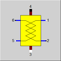
Display Option 2 |
 |
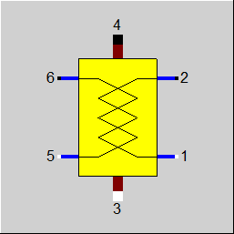
Display Option 3 |
 |
Display Option 4 |
Click here >>Component 62 Demo<< to load an example.