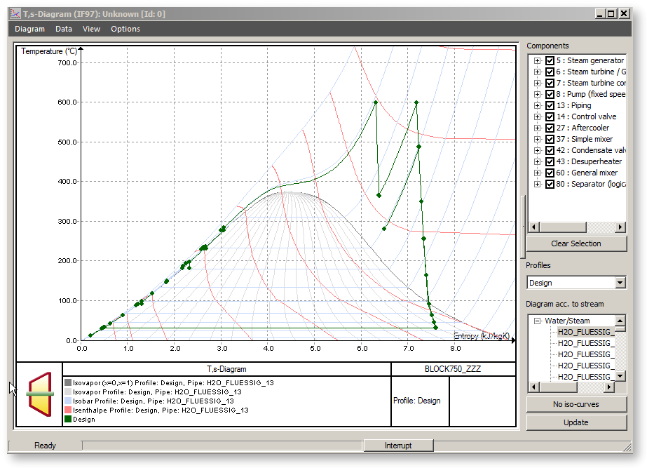

Diagrams serve the graphical representation of thermodynamic or computational connections. You can call them via the menu bar under ExtrasàDiagrams.
Under the menu item "ExtrasàDiagrams" an existing diagram can be loaded and a new diagram can be created and edited.
In EBSILON®Professional the following diagram types are available:
The XY-diagrams play a particular role because the visualization is performed by Microsoft Excel. The other diagrams are represented within EBSILON®Professional.
Every diagram-window is constructed as follows:

Menu bar
Menu bar consists of 4 points:
There are the following commands for data output under the menu item"Diagram" :
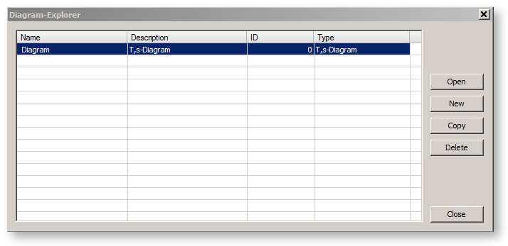
The command "DiagramàSelect ..." invokes the diagram explorer dialog, in which you can choose between the diagram configurations added to the currently loaded *.ebs file.
The complete configuration of a diagram can be saved, loaded and edited (independent of the diagram type) in the model file (*.ebs). Saving is done via menu item "Add current diagram..." in the diagram dialogue. Loading is done via menu item "Select diagram..." in the diagram dialogue. It is possible (as with profiles or EbsScripts) to configure, save and load (e.g. via diagram IDs) any number of diagrams. If inconsistencies are detected during loading (e.g. the objects saved in the configuration no longer exist), the user receives a corresponding error message. Editing the current diagram configuration is possible from the diagram dialogue GUI.

The command "DiagramàAdd current ..." invokes the diagram explorer dialog and enables to add the current diagram under specified name and ID to the currently loaded *.ebs file. Only the diagram configuration is added (and finally stored) to the *.ebs file, not the complete diagram curve data. The diagram data is created and the chart is re-drawn each time the stored diagram configuration is loaded (opened from diagram explorer).
The command "DiagramàUpdate diagram configuration..." enables to update (to save the currently made changes) the currently loaded diagram configuration. This is in turn possible only if the current diagram configuration is already added to the loaded *.ebs file. Attention: the changes are really stored on the disk only at storing the *.ebs itself.
The command "DiagramàSave as Bitmap..." exports the graphic of the diagram in various raster graphics formats (BMP, PNG, JPG, GIF etc.) in a file you specify.
Through the menu commands
of the diagram window you can print the active diagram, see a print preview of the active diagram, and select or configure the printer for printing the diagrams. The printer settings are global forEBSILON®Professional i.e. changes of the printer settings done in the diagram window are applied also to the main window and vice versa.
The menu option Print can also be selected by using the right mouse button.
Besides the ID, each diagram configurationhas a name and a description.
The following parameters belong to a diagram configuration and are saved:
o QT, cooling tower, controller convergence, controller output, HS, TS, logPH, HXI:
- List with names of the objects that are displayed in the diagram
o Only QT, HS, TS, logPH, HXI
- List with names of the profiles that are displayed in the diagram
Under the menu item "Data" there are the following commands:
The command "DiagramàCopy" exports the diagram’s data as semicolon separated list (csv-format) into the clipboard. After that you can import the data in a text file and load in Microsoft Excel.
Under the menu item "View" you can find the following commands to change the appearance and the type of the diagram:
The command
"ViewàZoom out" resets the diagram to the original size after zooming.
"ViewàGrid" switches a grid on or off.
"ViewàFilter for Fluid Properties" confines the diagram to the pipelines fitting the background picture. By default the pipes for any kind of fluids are displayed, independent of whether their type corresponds with the background picture. By a second clicking the filter is removed again.
"ViewàSelect current objects in model" is relevant for q,T diagrams only. This command enables the selection of those objects (heat exchangers) in the EBSILON model which are selected in the right field of the diagram dialog.
"ViewàSelect all objects in model" is relevant for q,T diagrams only. This command enables the selection of all objects (heat exchangers) in the EBSILON model which are shown in the right field of the diagram dialog.
"ViewàCarnot factor Diagram" is relevant for q,T diagrams only. This command enables the transformation of the current q,T representation, so that instead of temperature T the
Carnot factor = 1 - T/Tref is used as y-axis Here Tref - is the reference temperature.
Via the commands "Viewàh,s-diagram", "Viewàh,xi-diagram", "ViewàT,s-diagram" and "Viewàlog p,h-diagram" you can switch between these four diagram types.
Under the menu "Options" you can change the the properties of the diagram and especially the background colour of the diagram.
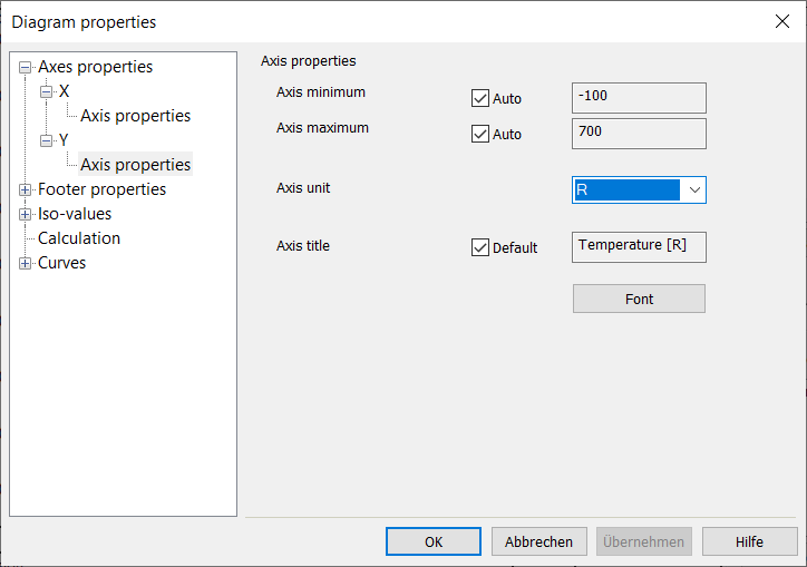
Via ”OptionsàProperties...” you can invoke the diagram properties dialog. In that dialog you have an access to the properties of axes, of the diagram footer, individual curves and curve sets, the iso-values (relevant for the iso line at h-s , T-s , log-p-h , h-xi diagrams) as well as to the calculation properties.

It it is possible to select a non-standard EBSILON unit for the X-axis or the Y-axis of the diagram. For this purpose, there is a combo box "Axis unit" for the respective axis (X and Y) in the diagram dialog under the menu "Options --> Properties...".
Via “OptionsàBackground colour…” the background colour of the diagram can be modified.
By clicking on the diagram area with the right mouse button you get the context menu with the following options:
Select
The cursor is switched to the highlight mode. This is the standard cursor mode. The cursor has the form of a hand. Tooltips are active in this mode.: if you move the mouse to a line, information is displayed, which line it is. In addition, you can choose lines and change their colour temporarily.
Zoom
The cursor is switched to the zoom-mode and takes the shape of a cross. By means of drag-&-drop and releasing the left mouse button, a window area can be selected ("drawn up"), which is the "zoom rectangle". The zooming is then done in this area when the left mouse button is released i.e. the smallest possible section of the screen is shown, which is included in the zoom rectangle. The values at the axes are changed automatically, also in their resolution (i.e. in the display of the decimal points).
Continued zooming shows more and more details of the diagram; a reverse zooming is not possible here. The standard size of the diagram can be shown again by using the following commands: Menu command: "ViewàStandard Size" of the diagram window or the menu option "Standard Size" by clicking the right mouse button.
Pan
The cursor is switched to the move-mode and takes the shape of an arrow cross. The diagram can be moved via drag and drop with the left mouse button.
Reset
After zooming a diagram, you can return to the original condition through this command.
You can call the print dialog through this command directly.
The options in the region on the right depend on the type of the diagram, so they are discussed at the different diagram types (see above).
The diagram-windows are non-modal, i.e. the EBSILON®Professional interface remains operable, while the diagram window is open. In particular, you can open and display further diagrams. However, diagrams are not updated automatically, if you make changes in the cycle or you run new calculations. Instead there is a button "Update" which can be clicked on for diagram to be re-generated and drawn using the current model results.
In particular, the generation of the iso curves in h-s, T-s, log p-h diagrams (isobars, isotherms, etc.) can become time-consuming in some fluids. Therefore, this generation does not run in the main thread for the diagram type h-s, T-s, log p-h, h-xi- and q-T, so that the diagram dialog window remains operational during generation.
The generation progress is displayed in a Progress Bar in the Status Bar. The generation can be aborted by clicking on “Interrupt”. The generation of the remaining diagram types (convergence, controller convergence, cooling tower diagram) runs synchronously in the main thread, and the control over the diagram dialog window is blocked as long as the diagram is being generated and drawn.
From EbsScript / EbsOpen a stored diagram can be loaded via its ID and the output can be redirected into an external file (raster graphics, BMP, PNG etc. or diagram data as text)
on the hard disk.
To do so, there are the functions
DiagramAsRasterGraphic (output of the diagram as raster graphics)
DiagramDataAsText (output of the diagram data as text).
Exporting the diagram data as text (either by copying into the clipboard or by means of EbsScript / EbsOpen functions) is possible in two different formats. The data can either
be exported as lines or as columns.
The export format is controlled via General Options à Diagram à Text Export Format.