In This Topic
Cooling Tower Diagram
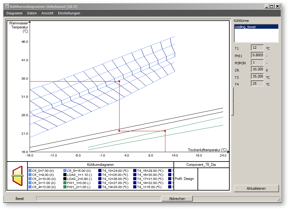
The cooling tower diagrams are used to visualize the actual working point of the cooling tower within the characteristic field entered. Before you can create a cooling tower diagram, you must do a calculation (simulation or validation).
Cooling tower diagrams are available for the components
- Cooling tower with characteristic field (78)
- Fan cooling tower (79)
No cooling tower diagram is available for the component 47 (Cooling tower with calculation according to the Klenke algorithm), because this component does not possess such a characteristic field.
Cooling tower diagrams are displayed through the menu command "ExtrasàDiagramàCooling tower diagrams". The cursor then assumes the shape of a cooling tower. The corresponding cooling tower diagram opens when you click on the a cooling tower (component 78 or 79).

The stored characteristic lines are displayed in the cooling tower diagram
- the green graphs display the stored characteristic lines, which describe the effect of air humidity (component 78) or the fan power (component 79) on the cooling tower behaviour
- the black graphs display the stored characteristic lines, which describe the dependency on the load (cooling water flow rate)
- the blue graphs display the characteristic lines, which describe the relationship between the cooling zone width and the warm water temperature. The light blue graphs are the stored characteristic lines, which enable you to read the warm water temperature from a given cooling zone width, the dark-blue ones are the graphs calculated from them, which enable reading the cooling zone width from a given warm water temperature
- the red lines display the position of the actual working point in the characteristic fields
Merkel cooling tower diagram
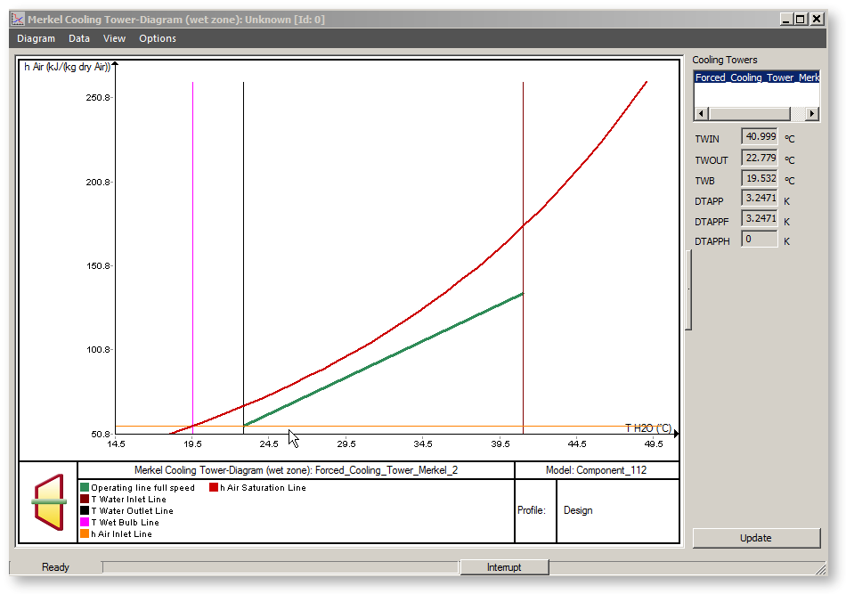
This type is relevant only for components 111 (natural draft cooling tower) and 112 (fan cooling tower). The Merkel cooling tower diagram can be accessed in the same way as other diagram types under the menu item Extras - Diagrams - Merkel Cooling Tower Diagram.
The saturation line of the air (air enthalpy plotted over the temperature) under the current atmospheric pressure as well as the change in the inlet and outlet states of the air (enthalpy) and the water (temperature) in the corresponding cooling tower are displayed in the diagram.


