
HS diagrams are used first of all to analyse the behaviour of turbines and compressors. In the HS diagram, the enthalpy is displayed over the entropy.Before you can create an HS diagram, you must do a calculation (simulation or validation).
HS diagrams are displayed through the menu command "ExtrasàDiagramsàHS-Diagrams". Here, you have different options for selection. The cursor assumes a special appearance for the selection, it appears with the short form "HS" or "HSX". The selection of transits in the diagram can be changedlater as well. There is also the possibility to display several profiles in the diagram.
In HS diagrams, the combustion components are displayed, too (with the transition airàflue gas).

By default, only the selected transits will be displayed in green colour. However, you can select as background image the Mollier-diagram of the respective fluid. The black lines are the curves with equal steam content (isovapors), the blue ones with equal pressure (isobars) and the red ones with equal temperature (isotherms) in the background image.
The corresponding value of the respective curve can be observed via tool-tip moving the mouse over the curve. The iso-values, the corresponding iso line is generated for, can be manipulated via OptionsàPropertiesàIso-values.

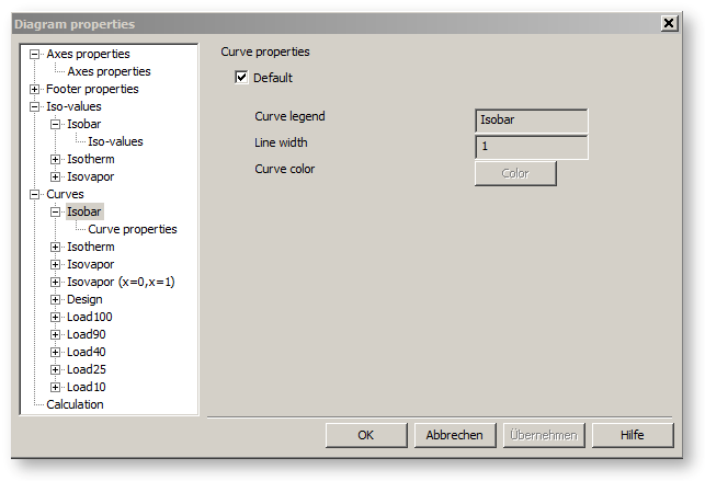
The legend, the colour and the line width of the individual curves and curve sets can be adjusted under OptionsàPropertiesàCurves.
