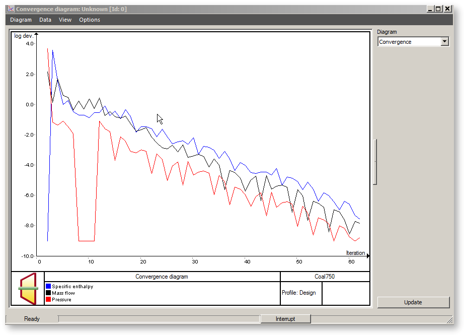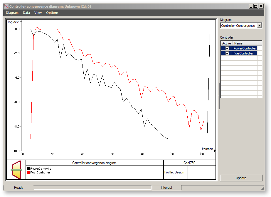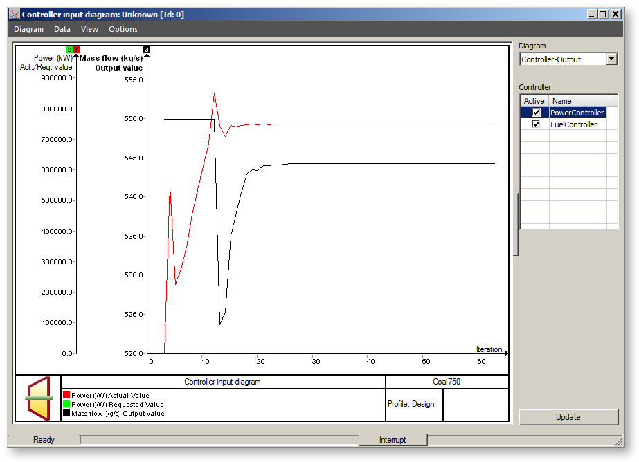

Convergence diagrams are the ideal tool for bad convergence cases, especially when mutually influencing controllers are present. They can directly observe the effects of processes like controller damping, delayed start and convergence relaxation and decide, what they can do to improve the convergence.
Convergence diagrams are displayed through the menu command "ExtrasàDiagramsàConvergence diagrams…" or by clicking on the button “Convergence” in the error-window.
If you do not have a controller in your cycle, there is exactly one diagram that displays the convergence behaviour of mass flow, enthalpy and pressure during the iteration process. The x-axis shows the number of iteration steps, the y-axis shows the maximum relative deviation from the corresponding quantity during the last iteration step. For instance, if you have a value of "-2" for the pressure, which is given for all the lines in the cycle, then the relative change in the pressure between the second-last and the last iteration step is less than or equal to 1% ( = 10 ^(-2)).

If you have a controller in your cycle, you can change between two additional types of convergence diagrams:
In the Controller-Diagram you can select one or more controllers. The names displayed correspond to the controller names used in the cycle. The diagram shows the convergence behaviour of these controllers respectively in different colours. This diagram is the same as the convergence diagram described above. The value on the y-axis is the relative deviation between the actual and the desired value in the corresponding iterations step.

You must select one controller for the Controller-Input-Diagram. For this controller, the desired value, the actual value and the input values are displayed. The desired and the actual values are displayed through the table on the left and through black grid lines, the input value through the table on the right and gray grid lines. Note that the desired value is constant for a controller of the type 39, but can deviate during the iteration for a controller of the type 12, where it is taken from another line of the cycle.
