
EBSILON®Professional Online Documentation


|
Line Connections |
|
|
|
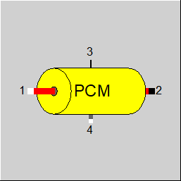
1 |
Main fluid inlet |
|
|
2 |
Main fluid outlet |
|
|
3 |
Heat transfer from main fluid (outlet) |
|
|
4 |
PCM-fluid definition (inlet) | |
General User Input Values Physics Used Characteristic Lines Results Displays Example
The component 166 models a PCM storage (here PCM stays for phase change material) including a heat exchanging part for charging / discharging the storage.. To properly understand the description it is highly important to clearly distinguish between the PCM-Fluid (the medium which changes its aggregate state and in which the latent heat is basically stored) and the Fluid (the working medium which flows through the heat exchanger charging / discharging the storage). Contrary to the working medium fluid the PCM-Fluid remains encapsulated within the storage. The working medium fluid flows through the component entering at PIN 1 and leaving at PIN 2. In this way the component 166 is connected to the modelled cycle.
The PCM-Fluid is defined at PIN 4. This can be done either by component 1 or component 33. See chapter PCM-Fluide for details. For modelling an ice storage one can use LibICE as PCM-Fluid on stream type two-phase-fluid.
The spatial alignment of Fluid-channel and the PCM-Fluid vessel can be realized in 2 different configurations:
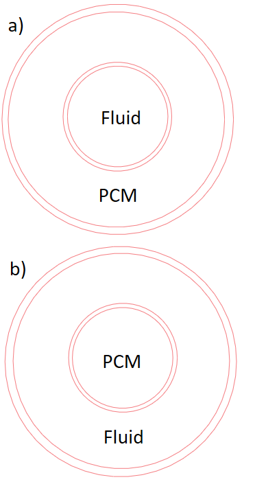
Figure 1: Spatial alignment. a) PCM outside, flow inside b) PCM outside, flow inside
It is essential to set the consistent geometric parameter values for the fluid channel and the PCM-Fluid vessel according to the spatial alignment. For FCONF=1 the diameter / side length of the fluid channel must be greater than the diameter / side length of the PCM-Fluid vessel. For FCONF=2 the diameter / side length of the PCM-Fluid vessel must be greater than the diameter / side length of the fluid channel.
Furthermore the following geometric types are available:
For different combinations of the input values FCONF, FGTYPFL, FGTYPPCM there are different alignments conceivable. Not all those alignments make sense and not all of them are implemented. For FGTYPPCM=2 (PCM-Fluid in balls) only FCONF=1 (PCM inside) is available. Further arrangements are shown in Figure 2. The combination of a square channel inside and a cylinder outside is not implemented.
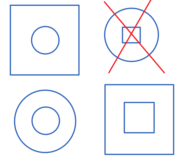
Figure 2. Schematic drawing of the implemented and not implemented (stricken in red) combination of the PCM-Fluid vessel and fluid channel geometry
Prior to Release 17, the numerical scheme for calculating the fluid temperatures was dependent on the FSPECM switch. For FSPECM=1 (fluid mass neglected) the scheme CDS (central differences) was always used. For FSPECM>1 (fluid mass taken into account) the upwind scheme was used.
The CDS scheme is more accurate than the upwind scheme. However, the upwind scheme is more stable for the internal convergence of the component.
From Release 17, the FNUMSC switch is available. This allows the user to select the numerical scheme independently of the FSPECM value. FNUMSC=0 corresponds to the upwind scheme, FNUMSC=1 corresponds to the CDS scheme.
If the inner iteration switches from CDS to Upwind due to detected convergence problems, the user is warned at the end of the simulation.
In the circuits saved with earlier EBSILON versions than Release 17, the value of the FNUMSC switch is set during loading depending on the FSPECM switch in order to reproduce the old results. However, this automatic setting of the switch does not work if FSPECM does not have a simple valid numerical value, but contains a reference (kernel expression) to other components, for example. In such a case, the user should set the FNUMSC switch himself so that the old results are reproduced.
An off-design pressure loss calculation based on the specific volume at the inlet of the component can lead to higher inaccuracies, if the temperature change between inlet and outlet is high and the flowing medium is compressible / gaseous.
This is why there is the FDPBASE switch, where the mean value of the specific volume between inlet and outlet can also be used and the nominal value V12N (the mean specific volume between inlet and outlet) can be used as a reference value.
When calculating a fluid at rest (e. g. standby mode of the storage tank), the heat conduction in the fluid must always be taken into account (FHC=1), whereas in the case of a flowing fluid in the storage tank neglecting the heat conduction in the fluid is justified (FHC=0).
For the heat exchange between the fluid elements in the storage tank, the material value tables of the fluid are used for the calculation of the thermal conductivity.
In addition, the thermal conductivity can be multiplied by a factor CLMFL. This may be necessary, for example, in the case of free convection in the storage tank.
|
FINST |
Flag: Determination of transient calculation modes |
|
FINIT
|
Flag: Initializing state =0: Global, which is controlled via global variable "Transient mode" under Model Options =1: First run -> Initializing while calculating steady state values |
|
FMODE
|
Flag: Calculation mode (design / off-design)
=0: Global |
|
FCONF
|
Geometry configuration details =1: PCM inside, flow outside =2: PCM ouside, flow inside |
|
LSTO |
Flow length of storage at FINIT=1 |
|
FGTYPPCM |
PCM vessel wall geometry type =0: tube =1: square channel =2: ball |
|
FSTOPCM |
Definition of PCM vessel wall geometry. Required for computing the wall mass and the heat exchanging area: =0: Specify the length LSTO, the heat exchanging area AWPCM and the wall mass MWPCM |
|
DIAIPCM |
Inner diameter / channel side length of the PCM vessel wall |
|
THWPCM |
Wall thickness of the PCM vessel |
|
AWPCM |
Heat exchanging area between PCM-Fluid and PCM vessel wall |
|
MWPCM |
PCM vessel wall mass (not equal to the PCM-Fluid mass!) |
| FPCMBALL |
Definition of the PCM ball geometry: =0: using THWPCM, DIAIPCM for single balls and PHI |
| NBALLS | Number of PCM balls |
|
FGTYPFL |
Fluid channel geometry type =0: tube =1: square channel |
|
FSTOFL |
Definition of Fluid channel wall geometry. Required for computing the wall mass and the heat exchanging area: =0: Specify the length LSTO, the heat exchanging area AWFL and the wall mass MWFL |
|
DIAIFL |
Inner diameter / channel side length of the fluid channel |
|
THWFL |
Wall thickness of the fluid channel |
|
AWFL |
Heat exchanging area between fluid and fluid channel wall |
|
MWFL |
Fluid channel wall mass |
|
FSPECM |
Flag: Handling of fluid mass = 1: Fluid mass neglectible |
|
FDATPCMV |
Specification of thePCM vessel wall material properties =1: constant according to RHOPCMV, LAMPCMV, CPPCMV =-1: according to FMPCMV =-2: according to kernel expressions ERHOPCMV, ECPPCMV, ELAMPCMV |
|
FMPCMV |
Specification of PCM vessel wall material : Material Properties of Steel |
|
RHOPCMV |
PCM vessel wall material density |
|
LAMPCMV |
PCM vessel wall heat conductivity |
|
CPCMV |
PCM vessel wall heat capacity |
|
ERHOPCMV |
Kernel expression PCM vessel wall material density |
|
ELAMPCMV |
Kernel expression PCM vessel wall heat conductivity |
|
ECPCMV |
Kernel expression PCM vessel wall heat capacity |
|
FDATFLV |
Specification of the fluid channel wall material properties
=1: constant according to RHOFLV, LAMFLV, CPFLV =-1: according to FMFLV =-2: according to kernel expressions ERHOFLV, ECPFLV, ELAMFLV |
|
FMFLV |
Specification of fluid channel wall material : Material Properties of Steel |
|
RHOFLV |
Fluid channel wall material density |
|
LAMFLV |
Fluid channel wall material heat conductivity |
|
CFLV |
Fluid channel wall material heat capacity |
|
ERHOFLV |
Kernel expression fluid channel wall material density |
|
ELAMFLV |
Kernel expression fluid channel wall material heat conductivity |
|
ECFLV |
Kernel expression fluid channel wall material heat capacity |
|
THISO |
Thickness of insulation |
|
LAMISO |
Heat conductivity of insulation |
|
FTSTEPS |
Controling the sub-time step =0: Scaling the sub-time step according to diffusion numberl and TLSF =1: By specification value TISPEP |
|
TLSF |
Sub-time step scaling factor based on theoretical limit |
|
ISUBMAX |
Maximum number of time sub steps for initialization |
|
IERRMAX |
Maximum allowed error for initializing step |
|
TISTEP |
Sub-time step |
| FNUMSC |
Numeric scheme =0: Upwind |
|
NFLOW |
Number of points in x-direction (flow direction) |
|
NRAD |
Number of points in y-direction (direction normal to flow) |
|
TMIN |
Lower limit for storage temperature (relevant for walls as well as PCM-Fluid) |
|
TMAX |
Upper limit for storage temperature (relevant for walls as well as PCM-Fluid) |
|
FSTAMB |
Flag: Definition of ambient temperature =0: Definition specification value (TAMB) |
|
TAMB |
Ambient temperature |
|
ISUN |
Index for solar parameters (e.g. component 117) |
|
FALPHI |
Determination of the inner alpha number to internal storage =0: according to ALPHI and part load exponent EX12 |
|
ALPHI |
Inner heat transfer coefficient |
|
EX12 |
Mass flow exponent for inner heat transfer coefficient |
|
EALPHI |
Kernel expression for Inner heat transfer coefficient |
|
FALPHO |
Determination of alpha outside =0: From constant value ALPHO |
|
ALPHO |
Outer heat transfer coefficient (to ambient) when FALPHO=0 |
|
EALPHO |
Kernel expression for alpha outside |
|
AOUTP |
The part of the outer surface being in contact to ambient |
|
CLMPCM |
Correction factor to heat conductivity of PCM-Fluid (to account for convection while PCM melting process) |
| FHC |
Fluid heat conductivity consideration =0: Neglected |
| CLMFL | Lambda fluid correction factor (e.g. due to free convection) |
|
FVOL |
Flag: Part-load pressure drop
=0: Only depending on mass flow |
| FDPBASE |
Pressure loss calculation for the off-design calculation =0: the mean value of the specific volume between inlet and outlet is used as the reference value |
|
DP12N |
Pressure drop (nominal, fluid flow) |
|
PPCM |
Pressure in PCM-Fluid |
|
FSTART |
Initialization of the temperature field (FINIT=1) =1: temperature of storage (shell and internal storage) equal TSTART |
|
TSTART |
Initial value of temperature (FINIT=1) |
|
FDIR |
Fluid flow direction =0: Normal |
|
TIMETOT0 |
Total time at start of calculation (Sum of previous time steps) |
| PHI | Void volume fraction - volume fraction of fluid channel not occupied by PCM balls |
|
M1N |
Fluid mass flow (nominal) |
|
V1N |
Specific volume at inlet (nominal) |
| V12N |
Specific volume averaged between inlet and outlet (nominal) - see FDPBASE |
The parameters marked in blue are reference quantities for the off-design mode. The actual off-design values refer to these quantities in the equations used.
Generally, all inputs that are visible are required. But, often default values are provided.
For more information on colour of the input fields and their descriptions see Edit Component\Specification values
For more information on design vs. off-design and nominal values see General\Accept Nominal values
|
T2BEG |
Averaged caloric temperature of the storage in the beginning of the time step |
|
T2END |
Averaged caloric temperature of the storage at the end of the time step |
|
QSTO |
Energy stored during time step (storage and fluid) |
|
QAV |
Average stored energy flow in time step (QSTO/TIMEINT) |
|
QAVI |
Average energy flow from fluid to storage |
|
QAVO |
Average energy flow from storage to environment |
|
RALPHI |
Used inner heat transfer coefficient fluid to storage |
|
RALPHO |
Used outer heat transfer coefficient (to ambient) |
|
RASTO |
Computed heat exchanging area fluid to storage |
|
RWDFL |
Computed fluid layer thickness |
|
RTHFL |
Computed thickness of fluid channel wall |
|
RWDPCM |
Computed PCM layer thickness |
|
RTHPCM |
Computed thickness of PCM vessel wall |
|
RMSTO |
Overall storage mass |
|
RMPCM |
Mass of PCM-Fluid |
|
RVFLUID |
Fluid volume |
|
MFLUID |
Fluid mass |
|
RTAMB |
Ambient temperature |
|
DIFNUMB |
Diffusion numberl (relevant for numeric stability and accuracy, has the same meaning as the input value of TLSF) |
|
TIMEINT |
Total integration time (current time step) |
|
TIMETOT |
Total time at end of calculation (time-series) |
|
TIMESUB |
Sub-time step length |
|
ISUB |
Number of sub-time steps in the current time step |
|
TISUBREC |
Recommended sub-time step length, derived presuming DIFNUMB=TLSF |
|
PREC |
Precision indicator: normalized difference between the heat transferred to fluid, the heat stored in the storage (PCM-Fluid + walls) and the heat flow to the environment |
| PRECPCM | Precision indicator for the calculation in PCM-Fluid |
The implementation of component 166 is based on 2D-Grid with Crank-Nicolson-Algorithm similar to component 119. Contrary to component 119 the storage of component 166 consists of multiple layers. Those layers include the fluid channel wall, PCM-Fluid itself and the wall of the PCM vessel. The PCM-Fluid layer has the highest thermal resistance and the highest thermal storage capacity. The PCM-Fluid layer is resolved in the direction normal to the flow by NRAD elements. The fluid channel wall and the PCM vessel wall are resolved each by just one element in the flow normal direction.
The PCM-Fluid, as soon as it becomes liquid, is able to recirculate which, in turn, causes free convection heat flow additionally to the heat conduction. The acceleration of the heat transfer due to convection can be taken into account in the simulation by means of the correction factor CLMPCM. The numeric solution of the heat equation on 2D-grid does not explicitly account for a flow of PCM-Fluid between the grid elements.
The time step length (defined by intervals in time-series) and the sub-time steps (defined in component 166 via FTSTEPS, TISTEP, TLSF) are important for the accuracy and stability of computation. The accuracy regarding the overall energy balance between the fluid and the storage is indicated by the result value PREC. The result value PRECPCM the accuracy of calculation in PCM-Fluid. An additional aid in setting the sub-time step length is provided by the diffusion number (result value DIFNUMB). It is recommended to set the sub-time step width so that the diffusion number does not exceed the value of 10. One can make use of the input value FTSTEPS and set it to 0 while setting the value of TLSF to 10 (standard value of TLSF).
All established PCMs (including ice) change their density / specific volume at phase transition (solid-liquid or liquid-solid) by approximately 9-11%. Due to this fact the volume occupied by the PCM layer in the storage changes as well. The volume change results in the changing of the heat exchanging area between fluid and storage. The PCM-Fluid mass is defined in the initial step of the time-series by the specification of geometry (definition of PCM vessel) and the initial temperature. The temperature value defines the PCM aggregate state and consequently the PCM density. From the known PCM-Fluid density and the PCM vessel volume the PCM mass is computed. This mass does not change in the following time steps.
All characteristic lines form a circular buffer. The user doesn´t have to take care of them.
Corresponding to this there are also result arrays.
Specification matrices MXTSTOPCM, MXLAMSTOPCM, MXCPSTOPCM, MXRHOSTOPCM and result matrices RXTSTOPCM, RXLAMSTOPCM, RXCPSTOPCM, RXRHOSTOPCM
The matrix MXTSTOPCM is linked to the result matrix RXTSTOPCM in the same way as the characteristic curves and result arraysmentioned above.
The distribution of the values in the storage and the fluids is stored in both matrices (default matrix MXTSTOPCM for time step t-1 and result matrix RXTSTOPCM for time step t).
For the structure of the matrices, see matrices of component 160.
 |
Display option 1 |
Click here>> Component 166 Demo << to load an example.