
EBSILON®Professional Online Documentation


|
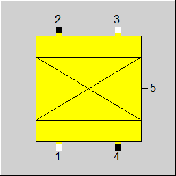
Line Connections |
|
|
|
1 |
Main inlet, normal flow direction |
|
|
2 |
Main outlet, normal flow direction |
|
|
3 |
Main inlet, reverted flow direction |
|
|
4 |
Main outlet, reverted flow direction |
|
|
5 |
Heat transfer from main fluid (outlet) |
|
|
6 |
Coupled thermal heat (inlet) |
|
General User Input Values Physics Used Characteristic Lines Results Displays Example
The component 165 can be used to model a thermal regenerator (e.g. cowper) / a bulk material storage. Thereby there is a difference between the internal storage (suffix "IS" in parameter names e.g. FDATAIS) and the shell (suffix "S" in parameter names e.g. FDATAS). The shell may have cylinder shape or be a square channel. The shell geometry determines the overall storage volume in which the internal storage material is enclosed.
The shell wall and the internal storage mass may consist of different materials and may have heat transfer coefficient values regarding the heat transfer to or from the working fluid medium. One can specify different material properties as well as heat transfer coefficients in the corresponding input fields.
For the alternating flow directions in the storage while charging and discharging phase there are PINs 1, 2 and 3, 4 as well as the flag FDIR provided . The component expects the working medium to either flow from PIN 1 to PIN 2 or from PIN 3 to PIN 4. A simultaneous specification of mass flow values > 0 on all four PINS does not make sense and is not allowed.
For the calculation of the pressure loss in the working medium flow there is an EBSILON standard algorithm with the nominal value DP12N and the Off-Design scaling as well as the formulas according to VDI Heat Atlas L1.6. The last method requires 2 additional parameters
An off-design pressure loss calculation based on the specific volume at the inlet of the component can lead to higher inaccuracies, if the temperature change between inlet and outlet is high and the flowing medium is compressible / gaseous.
This is why there is the FDPBASE switch, where the mean value of the specific volume between inlet and outlet can also be used and the nominal value V12N (the mean specific volume between inlet and outlet) can be used as a reference value.
The heat transfer coefficient to internal storage can be specified directly (parameters ALPHIIS, EALPHIIS, EXALPHIIS). Alternatively, one can use the formulas according to VDI Heat Atlas G9 (FALPHIIS=2). The last technique requires, like the pressure loss calculation, the characteristic diameter of the storage elements and the corresponding shape factor. The shape factor for the calculation of the heat transfer coefficient is defined by means of the parameters FSFALF and SFALF.
A heat flow can be specified at connection 6, which is included in the energy balance of the component. This can be used, for example, to model additional external heating or cooling (the heat flow may also be negative) of the storage tank.
Prior to Release 17, the upwind scheme was always used to calculate the fluid temperature.
The CDS scheme is more accurate than the upwind scheme. However, the upwind scheme is more stable for the internal convergence of the component.
From Release 17, the FNUMSC switch is available. This allows the user to select the numerical scheme independently of the FSPECM value. FNUMSC=0 corresponds to the upwind scheme, FNUMSC=1 corresponds to the CDS scheme.
If the inner iteration switches from CDS to upwind due to detected convergence problems, the user is warned of this at the end of the simulation.
When calculating a fluid at rest (e. g. standby mode of the storage tank), the heat conduction in the fluid must always be taken into account (FHC=1), whereas in the case of a flowing fluid in the storage tank neglecting the heat conduction in the fluid is justified (FHC=0).
For the heat exchange between the fluid elements in the storage tank, the material value tables of the fluid are used for the calculation of the thermal conductivity.
In addition, the thermal conductivity can be multiplied by a factor CLMFL. This may be necessary, for example, in the case of free convection in the storage tank.
|
FINST |
Flag: Determination of transient calculation modes |
|
FINIT
|
Flag: Initializing state =0: Global, which is controlled via global variable "Transient mode" under Model Options =1: First run -> Initializing while calculating steady state values |
|
FMODE |
Flag: Calculation mode (design / off-design)
=0: Global |
|
FALGS
|
Flag: Determination of transient calculation algorithms for the shell wall |
|
FALGIS |
Flag: Determination of transient calculation algorithms for the internal storage = 1: Crank-Nicolson-Algorithm = 4: Combined numerical and analytical solution |
|
FGTYP |
Shell wall geometry type =0: tube |
|
FSTO |
Shell wall geometry definition. Required for computing the mass and the heat exchanging area: =0: Length LSTO, area ASTO and mass MSTO are given |
|
LSTO |
Shell wall length in flow direction |
|
DIAI |
Shell inner diameter / channel side length |
|
THSTO |
Shell wall thickness |
|
ASTO |
Heat exchanging area between fluid and shell wall |
|
MSTO |
Shell wall mass |
|
PHI |
Free cross section fraction (void volume fraction or porosity) |
|
FV |
Outer surface to volume ratio of the internal storage |
|
FDPC |
Schalter zur Berechnung des charakteristischen (äquivalenten) Durchmessers der Speicherelemente =0: Berechnung mittels FV =1: gemäß DPC |
|
DPC |
Characteristic (equivalent) diameter of the storage elements (VDI Heat Atlas L1.6 Table 1) |
|
FSPECM |
Flag: Handling of fluid mass = 1: Fluid mass neglectible |
|
FDATAS |
Specification of the shell wall material properties =1: constant according to RHOS, LAMS, CPS =-1: according to FMSHELL =-2: accoring to kernel expressions ERHOS, ECPS, ELAMS |
|
FMSHELL |
Specification of shell wall material : Material Properties of Steel |
|
RHOS |
Shell wall material density |
|
LAMS |
Shell wall material heat conductivity |
|
CPS |
Shell wall material heat capacity |
|
ERHOS |
Kernel expression shell wall material density |
|
ELAMS |
Kernel expression shell wall material heat conductivity |
|
ECPS |
Kernel expression shell wall material heat capacity |
|
FDATAIS |
Specification of the internal storage material properties (bulk material, storage pattern elements) =1: constant according to RHOIS, LAMIS, CPIS =-1: according to FMINST =-2: according to kernel expressions ERHOIS, ECPIS, ELAMIS |
|
FMINST |
Specification of internal storage material : Material Properties of Steel |
|
RHOIS |
Internal storage material density |
|
LAMIS |
Internal storage material heat conductivity |
|
CPIS |
Internal storage material heat capacity |
|
ERHOIS |
Kernel expression internal storage material density |
|
ELAMIS |
Kernel expression internal storage material heat conductivity |
|
ECPIS |
Kernel expression internal storage material heat capacity |
|
THISO |
Thickness of shell insulation |
|
LAMISO |
Heat conductivity of insulation |
| FCALC |
Transient balance calculation mode =0: Separate solutions for shell and inner storage mass, the inner storage mass and the housing are balanced separately and the total fluid mass flow is divided between 2 parts according to the surface area proportions |
|
FTSTEPS |
Flag: Specification of (sub-) time steps =1: By specification value TISPEP |
|
ISUBMAX |
Maximum number of time sub steps for initialization (FINIT=1 and FALGIS=1) |
|
IERRMAX |
Maximum allowed error for initializing step (FINIT=1 and FALGIS=1) |
|
TISTEP |
Sub-time step (FALGIS=1 or FALGS=1) |
| FNUMSC |
Numeric scheme =0: Upwind |
|
NFLOW |
Number of points in x-direction |
|
NYS |
Number of points in storage wall normal direction for shell wall (FALGS=1) |
|
NYIS |
Number of points in storage wall normal direction for internal storage (FALGIS=1) |
|
TAUADJ |
Correction factor for the time constant of the storage wall (FALGIS=4 or FALGS=4) |
|
LAMADJ |
Multiplication factor to 1/LAMBDA - the walls heat conductivity resistance (FALGIS=4 or FALGS=4) Setting LAMADJ=0 is equivalent to neglecting the walls heat conductivity resistance: either the wall thickness is infinitely small or lambda value is infinitely high Setting LAMADJ=1 is equivalent to computing the walls heat conductivity with the original value of LAMBDA and wall thickness LAMADJ<1 leads to decreasing the walls heat conductivity resistance LAMADJ>1 leads to increasing the walls heat conductivity resistance |
|
TMIN |
Lower limit for storage temperature |
|
TMAX |
Upper limit for storage temperature |
|
FSTAMB |
Flag: Definition of ambient temperature =0: Definition specification value (TAMB) |
|
TAMB |
Ambient temperature |
|
ISUN |
Index for solar parameters (e.g. component 117) |
|
FALPHIS |
Determination of the alpha number to shell wall =0: according to ALPHIS and part load exponent EXALPHIS |
|
ALPHIS |
Inner heat transfer coefficient to shell wall |
|
EALPHIS |
Kernel expression for inner heat transfer coefficient to shell wall |
|
EXALPHIS |
Mass flow exponent for internal alpha number to shell wall |
|
FALPHIIS |
Determination of the alpha number to internal storage =0: according to ALPHIIS and part load exponent EXALPHIIS |
|
ALPHIIS |
Inner heat transfer coefficient to internal storage |
|
EALPHIIS |
Kernel expression for Inner heat transfer coefficient to internal storage |
|
EXALPHIIS |
Mass flow exponent for Inner heat transfer coefficient to internal storage |
|
FSFALF |
Determination of the shape factor for ALPHIIS calculation according to VDI Heat Atlas G9 =0: using value of SFALF |
|
SFALF |
Shape factor for ALPHIIS calculation according to VDI Heat Atlas G9 |
|
FALPHO |
Determination of alpha outside =0: From constant value ALPHO |
|
ALPHO |
Outer heat transfer coefficient (to ambient) when FALPHO=0 |
|
EALPHO |
Kernel expression for alpha outside |
|
AOUTP |
The part of the outer surface being in contact to ambient |
| FHC |
Fluid heat conductivity consideration =0: Neglected |
| CLMFL | Lambda fluid correction factor (e.g. due to free convection) |
|
FDP12 |
Pressure loss calculation =0 : DP12N |
|
FVOL |
Flag: Part-load pressure drop
=0: Only depending on mass flow |
| FDPBASE |
Pressure loss calculation for the off-design calculation =0: the mean value of the specific volume between inlet and outlet is used as the reference value |
|
DP12N |
Pressure drop (nominal) |
|
PHIDP |
Pressure drop shape factor of internal storage (FDP12=1) (VDI Heat Atlas L1.6 Table 1) |
|
FSTART |
Initialization of the temperature field (FINIT=1) =1: temperature of storage (shell and internal storage) equal TSTART |
|
TSTART |
Initial value of temperature (FINIT=1) |
|
FDIR |
Stream direction =0: normal, fluid flow from PIN 1 to PIN 2 =1: reverted, fluid flow from PIN 3 to PIN 4 |
|
DIRLAST |
Stream direction in the previous time step |
|
TIMETOT0 |
Total time at start of calculation (Sum of previous time steps) |
|
M1N |
Fluid mass flow (nominal) |
|
V1N |
Specific volume at inlet (nominal) |
|
V12N |
Mean value of the specific volume between inlet and outlet (nominal) - see FDPBASE |
The parameters marked in blue are reference quantities for the off-design mode. The actual off-design values refer to these quantities in the equations used.
Generally, all inputs that are visible are required. But, often default values are provided.
For more information on colour of the input fields and their descriptions see Edit Component\Specification values
For more information on design vs. off-design and nominal values see General\Accept Nominal values
|
TAVBEG |
Averaged caloric temperature of the storage in the beginning of the time step |
|
TAVEND |
Averaged caloric temperature of the storage at the end of the time step |
|
T2BEG |
Outlet temperature of fluid in the beginning of time step |
|
T2END |
Outlet temperature of fluid in the end of time step |
|
QSTO |
Energy stored during time step (internal storage, shell wall and fluid) |
|
QAV |
Average stored energy flow in time step (QSTO/TIMEINT) |
|
QAVI |
Average energy flow from fluid to storage |
|
QAVO |
Average energy flow from storage to environment |
|
RALPHIIS |
Used inner heat transfer coefficient fluid to internal storage |
|
RALPHO |
Used outer heat transfer coefficient (to ambient) |
|
RASTO |
Used overall heat exchanging area of storage (shell + internal storage) |
|
RTHSTO |
Equivalent plane thickness (internal storage) |
|
RMSTO |
Used overall mass of storage (shell + internal storage) |
|
RVFLUID |
Used flow volume of fluid |
|
MFLUID |
Mass of fluid in storage (FSPECM>1) |
|
PFLAV |
Average pressure in fluid |
|
HFLAV |
Average enthalpy in fluid |
|
TFLAV |
Average temperature in fluid |
|
RHOFLAV |
Average density of fluid (FSPECM>1) |
|
RTAMB |
Ambient temperature used in calculation |
|
BIOTIS |
Biot number internal storage |
|
TIMEINT |
Total integration time (current time step) |
|
TIMETOT |
Total time at end of calculation (time-series) |
|
DIRCUR |
Stream direction at current time step (0=normal, 1=reverted) |
|
PREC |
Precision indicator: normalized difference between the heat transferred to fluid, the heat stored in the storage (internal storage + shell wall) and the heat flow to the environment |
| RALPHIS |
Used inner heat transfer coefficient fluid to shell |
| BIOTS | Biot number shell |
The calculation of the component 165 is based on the simplification of the internal storage geometry. The real storage pattern of a regenerator can be replaced by the equivalent plate geometry. Doing so one has to keep equal the overall mass and the overall heat exchanging surface area of the real storage pattern and of the simplified plate.
The internal storage is specified by two parameters
Once fV, φ and the overall volume (storage pattern and the void volume) are known, the volume of the internal storage and its contact surface area can be computed. The results are used to define the equivalent plate. The equivalent plate represents the internal storage in the calculation of the heat transfer as well as heat charge and discharge.
The overall fluid flow is internally split according to the area ratio into part flows regarding the shell and regarding the internal storage. The sub-system fluid-shell wall and the sub-system fluid-internal storage are treated separetely in the simulation. Finally the mean values of temperature, enthalpy are obtained by average according to the mass fractions.
For the heat conduction calculations there are 2 alternative algorithms available for both the shell wall and the internal storage (control via parameters FALGS, FALGIS). See Component 119 for details.
All characteristic lines form a circular buffer. The user doesn´t have to take care of them.
Corresponding to this there are also result arrays.
Specification matrices MXTSTOS, MXTSTOIS and result matrices RXTSTOS, RXTSTOIS
The matrix MXTSTOS is linked to the result matrix RXTSTOS in the same way as the characteristics and result arrays mentioned above.
The distribution of the values in the storage and the fluids is stored in both matrices (default matrix MXTSTOS for time step t-1 and result matrix RXTSTOS for time step t).
For the structure of the matrices, see matrices of component 160.
 |
Display option 1 |
Click here>> Component 165 Demo << to load an example.