
|
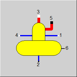
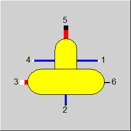
Line connections |
|
|
|
1 |
Main condensate inlet |
|
|
2 |
Feed water outlet |
|
|
3 |
Heating steam inlet |
|
|
4 |
Auxiliary condensate inlet (without throttle) |
|
|
5 |
Vapour mass flow loss (vent) |
|
|
6 |
Averaged liquid volume fraction (liquid level) during time step |
|
General User Input Values Physics Used Displays Example
This component can be used to model a deaerator. A more detailed option for a deaerator is also available in component 63.
If you have assigned vapour losses (vent), then these must be taken as water losses that need to be reintroduced into the system as makeup water in the right quantity and at the right place (otherwise no steady state is present). This can be handled very easily with a signal translator that registers the mass of vapour and translates it into the additional water connection.
With the new set value DP32F a fixed (i.e. load-independent) fraction of the pressure loss can be defined. This serves to take the filling level into consideration: As the steam is introduced below the water surface, there is a pressure difference between the pressure of the steam in the container and the pressure of the incoming steam, which does not depend on the mass flow but only on the filling level.
The pressure drop can also be adjusted via a kernel expression.
Component 9 also allows to model the feed water tank with deaerator in the transient case. The flag FINST can be used for this purpose. A thermodynamic equilibrium between the liquid and the gaseous phase is assumed.
The transient calculation requires the specification of the geometric details of the component. The fluid volume, wall storage mass, and exchange surface area between wall and fluid are calculated from the geometric details. The properties of the wall material like density, thermal conductivity, and heat capacity can either be specified from the stored library (flag FMAT) or by the user.
The heat exchange between the fluid and the tank wall and the temperature development in the tank wall over time respectively are also considered. For this purpose, identical algorithms as in Component 119 are used. There are 2 algorithms in component 9 for the computation of the wall temperature. Like in comp. 119 for FALGINST=1 the equation (2.3) is solved numerically using Crank-Nicolson-Algorithm . For FALGINST=4 the combined analytic and numeric method is used instead.
For the calculation of the inner heat transfer coefficient (ALPHI), the user can choose between the formulae for free convection available in the VDI Heat Atlas and own specifications, also e.g. in the form of a user function (EALPHI).
The transient mass balance considers a change of the filling level of the tank during the time step. For the mass balance, the user can decide between the specification of the
by means of the flag FSPIN. The calculated fill level is output as the volume proportion of the liquid phase in the total volume of the tank at connection 6 as mass flow M6.
Notes:
Vapour losses:
The vapour losses can now optionally be specified via specification value M5 (as before) or set on the line externally. Switching over between the two modes of calculation is effected by means of the flag FM5.
External Specification of the Pressure of the Auxiliary Condensate:
Previously, the pressure of the auxiliary condensate was always set by the feed water tank as the auxiliary condensate is at the same pressure level as the feed water at the outlet. When modeling, it was therefore necessary to place a control valve or a condensate valve on the auxiliary condensate line in order to decrease the pressure to the condenser level.
Mode: P4 given externally:
To simplify the modeling, there is now a mode “P4 given externally“ that can be set by means of the flag FP4. This mode allows to connect a line with a higher pressure on Pin 4. Within the feed water tank, the auxiliary condensate is then reduced to the condenser pressure. The result is the same as with an external control valve.
The new mode is now the default setting for newly inserted components. For existing models, FP4 is set to “P4=P2“.
| FINST |
Transient mode: Like in Parent Profile (Sub Profile option only) Expression 0: Transient solution (time series or single calculation) 1: Always steady state solution |
|
Steady state calculation |
|
|
DP32N |
Pressure drop of heating steam (by flow), (nominal) |
|
DP32F |
Heating steam pressure drop (by fill level) |
|
FP4 |
Throttling of secondary condensate =0: No throttling (P4=P2) |
|
FM5 |
Method for specification of exhaust vapour M5 = 0: Use specification value M5 |
|
M5 |
Vapour mass flow losses In case the value entered is greater than 5% of the water feed, the vapour mass flow is restricted to 5%. If FSPEC=1 (see below) is set, a higher value can also be set. |
|
FEDP |
Usage of EDP (off-design only) =0: Not used =1: Correction: DP32=DP32F+DP32N*(M3/M3N)^2*EDP =2: Replacement: DP32=DP32F+DP32N*EDP |
|
EDP |
Pressure loss function |
|
FMODE |
Flag for calculation mode =0: GLOBAL =1: local off-design = -1: local design |
|
FSPEC |
Handling of a possible available steam portion in the feed water = 0: Output of an error message (normal case), vapour loss remains as specified in M5 = 1: Steam portion is separated as vapour steam via line 5. For this specification, at least the vapour stem specified in M5 is extracted, and also more, if required. =-11: Consider mass and energy balances only =11 : Consider mass and energy balances and H4=H' only |
|
M3N |
Mass flow heating steam (nominal) |
|
Transient calculation |
|
| FINIT |
Flag: Initializing state =0: Global, which is controlled via global variable "Transient mode" under Model Options =1: First run -> Initializing while calculating steady state values |
| FALGINST |
Flag: Determination of transient calculation algorithms |
|
Physical dimensions |
|
| FGEOM |
Geometry configuration details =0: Storage tank only =1: Storage tank with deaerator shell |
| DIAMT | Inner diameter storage tank |
| LENGT | Length storage tank |
| THWALLT | Wall thickness storage tank |
| DIAMD | Inner diameter deaerator shell |
| LENGD | Length deaerator shell |
| THWALLD | Wall thickness deaerator shell |
| THISO | Thickness of insulation |
| MRINPART | Ratio of internal parts to wall mass |
|
Material properties |
|
| FMAT |
Wall material see Steel Grades =-1 : Properties calculated by Kernel Expression ERHO, ELAM, ECP |
| ERHO | Function for material density |
| ELAM | Function for material heat conductivity |
| ECP | Function for material heat capacity |
| LAMISO | Thermal conductivity insulation |
| FTTI |
Temperature used for material table lookups =0: Actual temperature at the end of time step |
|
Control parameters for transients |
|
| FTSTEPS |
Flag: Specification of (sub-) time steps =1: By specification value TISPEP |
| ISUBMAX | Maximum number of time sub steps for initialization |
| IERRMAX | Maximum allowed error for initializing step |
| TISTEP | Internal time (sub-)step |
| FFREQ |
Frequency of transient calculations =1: At each iteration step |
| NRAD | Number of points in wall normal direction (max. 30) |
| FSPIN |
Transient balance calculation mode 0: Liquid level given, mass flows computed 1: M1 given, liquid level computed 2: all mass flows given (M1, M2, M3... ), liquid level and degasser pressure P2, P3 calculated |
| WF | Liquid volume fraction (liquid level) at the end of the time step |
| WFMIN | Minimal liquid level |
| WFMAX | Maximal liquid level |
|
Heat transfer coefficients |
|
| FALPHI |
Determination of alpha inside 0: Internal formulas VDI Wärmeatlas Edition 11 F3 (free convection) 1: from constant value APLHI 2: from function EALPHI |
| ALPHI | Inner heat transfer coefficient (to fluid) |
| EALPHI | Function for alpha inside |
| FALPHO |
Determination of alpha outside 0: from specification value ALPHO 1: from function EALPHO |
| ALPHO | Outer heat transfer coefficient (to ambient) |
| EALPHO | Function for alpha outside |
|
Limits and ambient conditions |
|
| TMIN | Lower limit for storage temperature |
| TMAX | Upper limit for storage temperature |
| FSTAMB |
Definition of ambient temperature 0: by specification value TAMB 1: defined by reference temperature (comp. 46) |
| TAMB | Ambient temperature |
|
Initial conditions |
|
| FISTART | Specification of start temperature |
| TIMETOT0 | Total time at start of calculation |
The quantities marked in blue represent reference quantities for off-design.
Generally, all inputs that are visible are required. But, often default values are provided.
For more information on colour of the input fields and their descriptions see Edit Component\Specification values
For more information on design vs. off-design and nominal values see General\Accept Nominal values
Specification matrix MXTSTO and result matrix RXTSTO
The specification matrix MXTSTO is linked to the result matrix RXTSTO in the same way as the characteristic curves and result arrays mentioned above.
The distribution of the values in the storage and the fluids is stored in both matrices (default matrix MXTSTO for time step t-1 and result matrix RXTSTO for time step t).
For the structure of the matrices, see matrices of component 9.
|
Steady state solution. All cases |
||
|
For the 1st iteration: M3 = M3N F = (M3/M3N) ** 2 If GLOBAL = design, then F=1.0 DP32 = DP32N * F P2 = P3 - DP32 T2 = f'(P2) H2 = f (P2,T2) M2 = M1 + M3 + M4 - M5 Q2 = M2 * H2 P5 = P2 P1 = P2 P2 = P4 T5 = T2 H5 = f"(T5) Q5 = M5 * H5 M3 = ((M2*H2 - M1*H1 - M4*H4 + M5*H5))/H3 |
||
 |
Display Option 1 |
 |
Display Options 2 |
Click here >> Component 9 Demo << to load an example.