
EBSILON®Professional Online Documentation


|
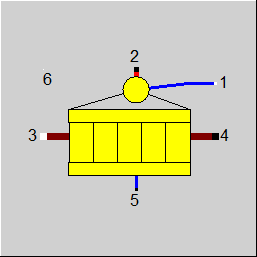
Line connections |
|
|
|
1 |
Condensate inlet |
|
|
2 |
Saturated steam outlet |
|
|
3 |
Flue gas inlet |
|
|
4 |
Flue gas outlet |
|
|
5 |
Drain / Blow Down |
|
Drain / Blow Down
|
6 |
Logic input for pump output (optional connection) |
Auxiliary lines for calculation:
|
H6 |
Water outlet pipe out of drum (saturated to mildly sub cooled) |
|
H7 |
Water outlet pipe out of pump ( Forced circulation) |
|
H8 |
Inlet into drum (two-phase mixture) |
General User Input Values Characteristic Lines Physics Used Displays Example
Saturated M2 is determined via M2=(Q87-M5*(H5-H1) ) / (H2-H1-CN*DH) (for derivation see section on Physics used), which results from the setting of the pinch point respectively k*A. This is an important statement because some modeling errors result from an over-determination of mass flow, when the user tries to enforce M2 via component 1 or 33.
Or in other words, the setting of the pinch point respectively k*A gives the saturated steam mass flow M2.
However, for M2 a user-entry of a starting value M2N is necessary in the design case. This should lie in the range of the expected steam production. This starting value should not be 0. After the design calculation, the start value entered for M2N is replaced by the calculated nominal value.
In the case of this component, the design via an ”effectiveness” factor is possible. It refers to the theoretically possible maximum heat exchange (for an infinitely large heat exchanger surface area). Thus an effectiveness of 0.8 means that 80 percent of the theoretically possible heat is exchanged.
Pressure drop limitations in off-design (Extras --> Model Options--> Calculation -->Relative pressure-drop maximum) :
As the pressure drop rises quadratically with the mass flow, pressure drops that are significantly too high can quickly arise in the event of a transgression of the nominal mass flow. These will then cause phase transitions and convergence problems. For this reason, pressure drop limitations have been installed.
Pin for Pump Power:
There is now an optional Pin 6 where the pump power is output. Depending on the desired level of detail of the modeling, a mechanical shaft, an electric line or a logic line can be connected.
When connecting a shaft, the isentropic efficiency of the circulating pump can be entered in specification value ETAIN and the motor can be modelled separately. Otherwise, the efficiency of the motor should also be considered in ETAIN.
The component only writes the power on Pin 6. When connecting a shaft and electric line respectively, default values are then used for frequency, voltage, current type, and phase (unless the setting of default values on shafts and electric lines has been disabled by the respective model option). If required, however, the desired values can be set by means of a start value (Component 33).
With Ebsilon, counterclockwise rotating processes can be mapped with similarly good convergence properties as clockwise rotating processes.
In the case of clockwise rotating processes, it is the condenser component that offers the option of directly calculating the pressure at which the condensation enthalpy is exactly high enough for the released condensation heat to be dissipated by the cooling water.
The drum components 20 and 70 can also calculate this directly.
However, an internal iteration is required for this (as with the condenser). The parameters START, CHL and ITSTEP are available for fine-tuning this internal iteration.
The DERIVLEV parameter is also available for convergence tuning, which can be used to set when the partial derivatives are to be included in the system of equations in pressure calculation mode. These are activated if the calculated pressure differs by less than DERIVLEV compared to the previous iteration step during the iteration. As the dependency is very sensitive (in the example circuit, the pressure changes by 100 mbar if the mass flow only changes by 1 g/s), the default value was set to 0. However, there may be circuits in which this parameter provides improvements.
There are two variants for the internal iteration after the pressure:
Also for this component there has been a modification in design:
In the case of shape 2, the flue gas inlet and outlet have been swapped to be able to model waste heat boilers top-down without the steam drum having to be upside down.
In the case of shapes 3 and 4, the pump is omitted in the design.
In the case of shape 5, the steam drum is situated above the flue gas path.
Flag FTAPPN allows the user to specify whether the feed water temperature is specified outside the component or whether the approach temperature is entered.
A kernel expression can be used as an alternative to the adaptation polynomial. The control is effected via the Flag FADAPT.
Usually, heat exchangers are designed in Ebsilon by specifying the terminal temperature differences or temperatures to be achieved. In an iterative process, the transferred amount of heat and the product of heat transfer coefficient and surface area (k*A) characteristic for the heat exchanger are calculated from this. Its nominal value KAN then serves to calculate the temperatures in off-design calculations. It is not necessary to know the individual values k and A here.
In the case of the components ECO/Evaporator/Superheater (exponents, Component 61), Duplex heat exchanger (Component 62), and Evaporator with steam drum (Component 70), however, the off-design behaviour is defined by exponents of heat transfer coefficients AL12 and AL34. As k can be calculated from it, the heat exchanger surface area A is available as well.
This has been used to implement a design calculation via the specification of the surface area. It is, however, essential to correctly specify the nominal values for the heat transfer coefficients AL12N and AL34N, which had only an effect on the partial load behaviour before to implementation of AN (area).
For the Evaporator with steam drum (Component 70), AL12N (used only for area calculation) has been newly implemented as a specification value, as it was not required before (because Al12N>>AL34N for the evaporator).
The specified surface area AN is only used for the design calculation to determine KAN from it. In the off-design calculation KAN is then used for the calculation.
Up to release 10.0, a pinchpoint violation was only determined subsequently in partial load, i.e. KA was calculated for the respective load case and from this the transferred heat quantity and then it was checked whether this heat quantity can be transferred at all at the correct temperature level. Since in the case of evaporation or condensation the temperature remains constant despite heat input or heat removal, there are cases where heat transfer is not physically possible despite the overall balance being correct. In this case, an error message was issued in Ebsilon.
The calculation has now been changed in such a way that the transferred heat quantity is reduced as far as it is still physically possible, with the minimum pinch point
can be set in a default value PINPMIN. This results in a correspondingly reduced KA.
The user is informed of this by a warning message ("KA reduced to avoid pinchpoint violation") and can then adjust the part-load characteristic curve or the part-load exponent for KA accordingly so that the warning no longer occurs. The advantage, however, is that one gets a physically possible result in any case.
Furthermore, at the end of the calculation there is a check if there is a pinch point violation due to curved course of Q(T) (caused by significant changes of cp depending on the temperature). This can be verified by dividing the heat exchanger into individual sections.
This case can occur, for example, when on the hot side the cp at the inlet is significantly smaller than at the outlet (for example, steam that has a cp of about 2 kJ/kgK at high superheat, but more than 5 just above the boiling line). This means that this steam provides more heat at a lower temperature level than at a high one. At appropriately low degrees, this can be a limitation on the amount of heat transfer that is possible.
The QT diagrams take into account the non-linearity (curvature of the curves) in areas without phase change.
The flag FSPEC (deprecated) has been divided into two flags:
Note:
When loading a model that was created with Release 11 (or older), the corresponding values for FSPECD, and FIDENT are determined from the value of the flag FSPEC, and
FSPEC is set to “void” (-999). The model then calculates the same result values. If required, however, the flag FSPEC can still be used as well.
To remove ambiguity, the terms “primary side” and “secondary side” respectively have been replaced by “cold side” and “warm side” in the input screens. The cold side (previously “primary”) is the flow from Pin 1 to Pin 2 that is heated. The warm side (previously “secondary”) is the flow from Pin 3 to Pin 4 that gives off the heat.
The effectiveness method for the design is available for the Evaporator with Steam Drum (Component 70) . In analogy to other heat exchangers, this option is selected via the flag FSPECD=0.
In the case of Components 25, 26, 27, 51, 55, 61, 70, 124, and 126 a calculation of the effectiveness in the context of the heat exchanger calculation is effected for other design methods as well (however, not in identification mode).
REFF is the ratio of the actual heat transferred to the theoretical maximum in case of infinite size of the heat exchanger surface.
A result value REFF has been implemented for this. In the design case, the calculated effectiveness is also stored in specification value EFF when the reference values are taken over.
Note on Component 70 :
Design in the Case of Concurrent Flow see Heat Exchanger General Notes:
The heat exchanger (Components 70) it is possible to carry out a design via the upper and lower terminal temperature difference also in the case of concurrent flow.
Flag FDQLR
You can use the FDQLR flag to define how DQLR (factor for modeling heat losses) should be interpreted.
Note on mixtures as working fluid:
In addition to the boiling temperature TSAT, this component also displays the dew point temperature TTAU as result value. In the case of mixtures as working fluid, the two temperatures may be different.
Performance factor RPFHX
The quotient from the current value for the heat transfer capability k*A (result value KA) and the k*A expected in the respective load point due to the component physics and characteristic lines respectively (result value KACL) serves to assess the condition of a heat exchanger.
The quotient KA / KACL is displayed as result value RPFHX.
|
FSPECD |
Calculation method in design-case =0: Effectiveness given as EFF |
|
FIDENT |
Component identification (only in off-design) =0: No identification mode, in off-design the steam generation and flue gas outlet temperature are calculated =2: M2 given externally in all load cases, KA calculated =4: Outlet temperature of hot stream (T4) given externally in off-design, KA calculated |
|
FCIRC |
Circulation method =0: Natural circulation |
|
EFF |
Effectiveness |
| FAA | Usage of area and alpha numbers =0: Determine AL12N, AL34N, EX12 and EX34 according to fluid =1: Use specification values AL12N, AL34N, EX12 and EX34 =2: Determine AL34N, EX34 and EX12 according to fluid, use AN to calculate AL12N =3: Determine AL12N, EX12 and EX34 according to fluid, use AN to calculate AL34N =4: Use specifiations AL34N and AN to calculate AL12N (and use EX12 and EX34) =5: Use specifiations AL12N and AN to calculate AL34N (and use EX12 and EX34) |
|
AN |
Heat transfer area (nominal) |
|
FTAPPN |
Flag for specification of approach temperature in design =0: By specification value TAPPN =1: T1 given externally |
|
TAPPN |
Approach temperature difference (nominal) TAPPN = Tsat(P-drum) - T(Economizer-exit) for H(ECOexit) in the design case applies { if TAPPN > 0.01 then { H(Economizerexit) = H(Tsat(Pdrum) -TAPPN) } if TAPPN <=0.01 then { H(Economizerexit) = from Economizer-heat balance } } for H(Economizerexit) in the off-design case applies { H(Economizer-exit) = from Economizer-heat balance } |
|
FDP12RN |
Water side pressure drop method =1: absolute : calculated by DP12N=DP12RN |
|
DP12RN |
Pressure drop of internal circulation (nominal) [absolute or relative to P1] DP12N is the pressure loss, which must be compensated by a circulation pump For a natural circulation boiler, DP12N is set to 0. |
|
FDP34RN |
Gas side pressure drop method =1: absolute : calculated by DP34N=DP34RN |
|
DP34RN |
Pressure drop line 34 (nominal) [absolute or relative to P3] |
| FSPECP |
Pressure calculation in off-design =0: P2 given, M2 calculated |
| START | Start value |
| CHL | Change per iteration limited by this factor |
| ISTEP | Pressure recalculation each ISTEP step(s) |
| DERIVLEV | Partial derivatives are activated if pressure deviation falls below this value (see above) |
|
FDQLR |
Heat loss handling =0: Constant (DQLR*QN in all load cases) |
|
DQLR |
Heat loss (relative to the heat transferred) |
|
FDRAIN |
Handling of blow down =0: Blow down flow rate given by specification value M5 =1: Blow down fraction given by specification value M5M2 =2: Blow down given externally =3: Blow down mass flow given by function EDRAIN |
|
M5 |
Blow down mass flow (absolute) |
|
M5M2 |
Blow down mass flow (relative to M2) (related to the saturated steam mass flow) M5=M5M2*M2 |
|
EDRAIN |
Function for blow down mass flow |
|
ETAIN |
Isentropic efficiency of the circulation pump (no characteristic line used: ETAI=ETAIN) |
|
CN |
Circulation number of the drum CN= M6/M2 M6=Water mass flow from the drum to the evaporator inlet |
|
FVOL |
Partload pressure drop =0: Only depending on mass flow DP/DPN = (M/MN)**2 =1: Depending on mass and volume flow DP/DPN = V/VN*(M/MN)**2 =2: constant pressure drop (equal nominal value) |
|
FMODE |
Calculation mode =0: Global =1: local off-design (i.e. always off-design mode, even when a design calculation has been done globally) =2: special local off-design (Special case for compatibility with the earlier Ebsilon-versions, should not be used in new models, because the results of the real = -1: local design |
|
FFLOW |
Direction of flow, see Heat Exchanger General Notes: =0: Counter Current flow =1: Concurrent flow =2: Cross flow |
|
NROW |
Number of rows (for cross flow) |
|
NPASS |
Number of passes (for cross flow) |
|
FARR |
Arrangement of passes (input for cross flow) =0: Counter Current flow =1: Concurrent flow |
|
AL12N |
Cold side heat transfer coefficient (used only for area calculation) |
|
AL34N |
Hot side heat transfer coefficient line 3 to 4 (nominal) |
| EX12 |
Mass flow exponent of AL12 AL12 = AL12N*(M1/M1N**EX12) |
|
EX34
|
Mass flow exponent of AL34 AL34 = AL34N*(M3/M3N**EX34)* (1 - (TM34N-TM34)*5E-4/°K) |
| DAL34DT | Additional partial load gradient for AL34 - see component 61 The temperature dependency of AL34 can thus be influenced - default value up to release 16: 0.0005 As the temperature dependency is calculated using the radiation formula when AL34RN is specified, it makes sense to set DAL34DT=0 in this case. Otherwise, both corrections are carried out. |
|
FADAPT
|
Flag for using the adaptation polynomial ADAPT/ adaptation function EADAPT =0: Not used and not evaluated =1: Correction for k*A [KA = KAN *K/KN* polynomial] =2: Calculation of k*A [KA = KAN * polynomial] =1000: Not used, but ADAPT evaluated as RADAPT (Reduction of the computing time) = -1: Correction for k*A [KA = KAN * K/KN * adaptation function] = -2: Calculation of k*A [KA = KAN * adaptation function] = -1000: Not used, but EADAPT evaluated as RADAPT (Reduction of the computing time) |
|
EADAPT |
Adaptation function for KA |
|
FFU |
On-/Off switch =0: Heat-exchanger off (no heat transfer, but pressure losses) =1: Heat-exchanger active |
|
PINPMIN |
Minimum value for the pinch point (KA is reduced automatically if the pinch point would fall below this value) |
|
PINPN |
Pinch point (nominal): T4-Tsat(P7) with P7=P1+DP12N Please note that only FFLOW = counter current flow is allowed only for the calculation mode FMODE=GLOBAL where PINPN is used |
|
FSPEC (deprecated) |
Specification combi switch (deprecated) = -999: unused (FSPECD and FIDENT used instead) old values: =0: Forced circulation, user specifies EFF in design =10: Forced circulation, user specifies the pinch point-temperature PINPN in design =11: Natural circulation, user specifies the pinch point-temperature PINPN in design =20: Forced circulation, M2 is specified (e.g. by component 33) in design =21: Natural circulation, User specifies M2N, which determines M2, in off-design =31: Natural circulation, heat transfer area (nominal) AN given in design |
|
KAN |
Heat transfer coefficient * area (nominal) , Design Heat Transfer Capability |
|
QN |
Generated heat flow |
|
M2N |
saturated steam mass flow |
|
M3N |
Hot side mass flow (nominal) |
|
TM34N |
Medium temperature of flue gas (nominal) TM34N=(T3N+T4N)/2 |
|
V1N |
Specific volume at point 1 (nominal) |
|
V3N |
Specific volume at point 3 (nominal) |
|
P1N |
Pressure at point 1 (nominal) |
|
P3N |
Pressure at point 3 (nominal) |
The identification value that is marked in blue is a reference quantity for off-design mode. The actual off-design values refer to these quantities in the equations used.
Generally, all inputs that are visible are required. But, often default values are provided.
For more information on colour of the input fields and their descriptions see Edit Component\Specification values
For more information on design vs. off-design and nominal values see General\Accept Nominal values
The saturated steam production is determined by an iteration procedure. M2N is taken as start value, which should have the same order of magnitude as M2 and M2N. Both quantities should not differ by a factor of more than 3-5.
TM34 = 0.5*(T3+T4)
FK2=(1-.0005*(TM34N-T34N))*(M3/M3N)**EX34
1 / KN = 1/ AL34N
1 / K = 1/(AL34N*FK2)
KA / KAN = K / KN
All cases |
||
|
|
if FDP12RN=relative, then {DP12N=P1*DP12RN} else {DP12N=DP12RN} if FDP34RN=relative, then {DP34N=P3*DP34RN} else {DP34N=DP34RN} |
|
|
Design case (Simulation flag: GLOBAL = design case AND FMODE = design case) |
||
|
|
Condition: FFLOW = counter current PH8=PH6=P5=P2=P1 T2=T5=TH6=TH8=fsat(P1) T1= T2-TAPPN H1=f(P1,T1) H2=fsat(P2,T2,X=1) H5=fsat(P5,T5,X=0)
SH6 = f(PH6,TH6) PH7=PH6+DP12N SH7 = f(PH7,SH6) DHS = H7S H6 DH = DHS/ETAIN HH7 = H6 + DH T7 = f(P7,H7)
P4 = P3 - DP34N T4=T7+PINPN H4=f(P4,T4) M4=M3 Q3=M3*H3 Q4=M4*H4 QN= Q3-Q4 Q87=(Q3-Q4) *(1-DQLR)
Determination of M2 and QPUM
{ M2*H2-M1*H1+M5*H5-QPUM=Q87 M1=M2+M5 QPUM= DH*MH6 MH6 = M2*CN }
M2=(Q87-M5*(H5-H1) ) / (H2-H1-CN*DH)
MH8=MH7=MH6
QPUM= DH*MH6 QH7=M7*H7 }
DTLO = T4 TH7 (for FFLOW = counter current) DTUP = T3 TH8 (for FFLOW = counter current)
LMTD = (DTUP - DTLO)/(ln(DTUP) - ln(DTLO)) KAN = DQ/LMTD KAN*LMTD = MH8*H8 MH7*H7 KAN*LMTD = (M3*H3 - M4*H4)*(1 - DQLR) |
|
|
Off-design case (Simulation flag: GLOBAL = off-design case or FMODE = off-design case) |
||
|
|
TOL = 0.00001 if FVOL= without, then { F1 = (M1/M1N) ** 2 if FMODE=1, then F1=1.0
F3 = (M3/M3N) ** 2 if FMODE=1, then F3=1.0 }
if FVOL= with, then { F1 = V1/V1N*(M1/M1N) ** 2 if FMODE=1 then F1=1.0
F3 = V3/V3N*(M3/M3N) ** 2 if FMODE=1, then F3=1.0 }
PH8=PH6=P5=P2=P1 T2=T5=TH6=TH8=fsat(P1) T1=f(P1,H1) H2=fsat(P2,T2,X=1) H5=fsat(P5,T5,X=0) SH6 = f(PH6,TH6) PH7=PH6+DP12N*F1 SH7 = f(PH7,SH6) DHS = SH7 HH6 DH = DHS/ETAI HH7 = HH6 + DH TH7 = f(PH7,HH7)
P4 = P3 - DP34N*F2 M4=M3
if FMODE = off-design, use KAN and characteristic line, then { Marking1 TM34 = 0.5*(T3+T4) FK2=(1-.0005*(TM34N-T34N))*(M3/M3N)**EX34 KN = 1/ AL34N K = 1/(AL34N*FK2) }
if FMODE = off-design: use KAN, no characteristic line, then { K = KN}
KA=KAN*K/KN Iteration1{ H4 = (Q3 Q87/(1-DQLR) )/M4 T4 = f(P4,H4)
DTLO = T4 TH7 (for FFLOW = counter current) DTUP = T3 TH8 (for FFLOW = counter current) DTLO = T4 TH8 (for FFLOW = concurrent flow) DTUP = T3 TH7 (for FFLOW = concurrent flow) LMTD = (DTUP - DTLO)/(ln(DTUP) - ln(DTLO)) QQ = KA * LMTD DQQ_1 = DQQ DQQ = Q87 - QQ
regula - falsi method { Size = (Q87 Q87_1)/(DQQ - DQQ_1) for iteration step 1: Size of the last global iteration step Q87X = Q87 - DQQ * Size Q87_1 = Q87 Q87 = Q87X }
DQ = |DQQ /((Q87+QQ)*.5)| if DQ < TOL, then end iteration 1 else continue the iteration }
KA*LMTD = MH8*HH8 MH7*HH7 KA*LMTD = (M3*H3 - M4*H4)*(1 DQLR) For FMODE = off-design, use KAN and characteristic line go to Mark 1, till convergence occurs
Determination ofM2 and QPUM
{ M2*H2-M1*H1+M5*H5-QPUM=Q87 M1=M2+M5 QPUM= DH*MH6 MH6 = M2*CN }
M2=(Q87-M5*(H5-H1) ) / (H2-H1-CN*DH)
M1=M2+M5 MH6 = M2*CN QPUM= DH*MH6 M7=M6 QH7=MH7*HH7 |
|
| Performance | Short Name | Dimension |
|
Heat given to cold stream (incl. heat from pump and to drain) |
Q21 | kW |
| Transferred heat | QT | kW |
| Heat delivered from hot side flow | Q34 | kW |
| Performance factor heat transfer | RPFHX | - |
| Heat Transfer | ||
| Heat transfer coefficient *area | KA | kW/K |
| Heat transfer coefficient | K | W/m2K |
| Heat transfer area | A | m2 |
| Mean log temperature difference | DTM | K |
|
Lower terminal temperature difference |
DTLO |
K |
| Upper terminal temperature difference | DTUP | K |
|
Alpha number 34 (operation) |
AL34 | W/m2K |
| KA according to component specific off design behaviour | KACL | kW/K |
| Calculated effectiveness (-actual heat transfer / theoretical maximum in case of infinite size) | REFF | - |
| Part Load | ||
|
Relative steam mass flow (Ratio of current steam production to steam production in the design case) |
M2M2N | - |
|
Relative hot side mass flow (Ratio of the current exhaust gas mass flow to the exhaust gas mass flow in the design case) |
M3M3N | - |
| Peripheral Results | - | |
| Circulation pump power | QPUMP | kW |
| Volume flow at cold side inlet | VM1 | m3/s |
| Volume flow at hot side inlet | VM3 | m3/s |
| Steam quality (X) at cold side outlet |
X2 |
- |
| Heat transfer to flow 12 up to intermediate point | Q12IP | kW |
| Temperature at flow 12 at intermediate point | T12IP | °C |
| Temperature difference between flow 34 and flow 12 at intermediate point | DTIP | K |
| Result of ADAPT / EADAPT | RADAPT | - |
| Saturated liquid enthalpy or max (HSAT,H1) | HLS | kJ/kg |
| Boiling temperature | TSAT | °C |
| Dew point temperature | TDEW | °C |
| Boiling pressure | PSAT | bar |
| Saturated liquid enthalpy or max (SSAT, S1) | SLS | kJ/kgK |
Use option 1 or 2 in case of forced circulation, options 3 to 5 in case of natural circulation.
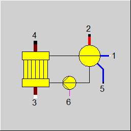 |
Display Option 1 |
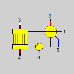 |
Display Option 2 |
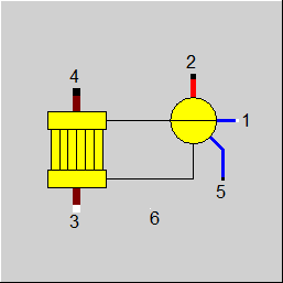 |
Display Option 3 |
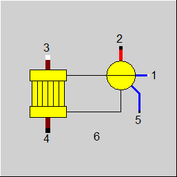 |
Display Option 4 |
 |
Display Option 5 1 |
Click here >> Component 70 Demo << to load an example.