
|
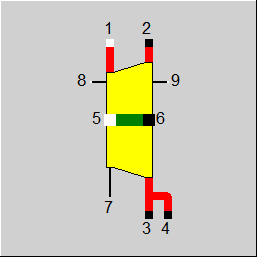
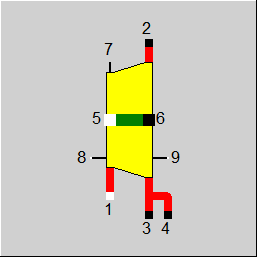
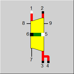
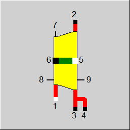
Line connections |
|
|
|
1 |
Inlet |
|
|
2 |
Outlet |
|
|
3 |
Extraction 1 |
|
|
4 |
Extraction 2 |
|
|
5 |
Shaft entry |
|
|
6 |
Shaft exit |
|
|
7 |
Outlet for controlling purposes Information exit for outlet pressure (P2) or the sum of the escaping mass flow |
|
|
8 |
Inlet for the measured pressure at line 1 |
|
|
9 |
Inlet for the measured enthalpy at line 1 |
|
General User Input Values Characteristic Lines Physics Used Displays Example
Component 56 models a turbine stage, a set of stages or a section: e.g. from entry to the first extraction, or from extraction i to extraction i+1, or from last extraction to exit. The extraction in this case is the connection provided irrespective of whether steam really bled out or not.
The turbine is defined by pressure at the inlet and the efficiency. In most cases, the pressure at the outlet is defined by the pressure at the inlet of the following turbine stage. In the case of the last turbine stage, the pressure at the outlet has to be defined by using a component 33.
When the exhaust steam at a last turbine stage is not led through connection 2 e.g. for condensation into the condenser, but instead through one of the two extraction connections, connection 2 has to be equipped with a blind line and the mass flow must be defined as zero using component 33 (start value).
The properties described so far do not differ from the properties of component 6 (steam turbine type 1).
The flow characteristic (inlet pressure as a function of mass flow) is determined by means of the conical law of Stodola.
At partial load, component 56 calculates inlet pressure P1 as a function of mass flow, outlet pressure and its specific volume from the Stodola Law:
See also and for the formulation of the Stodola law: Turbines - OffDesign - Stodola
In the chapter "Part load calculation of the steam turbine", M1N, P1N, P2N and V1N designate the nominal values in the design case or M1, P1, P2 and V1 the corresponding quantities under the current conditions.
As in the design case, the outlet pressure P2 is always determined by external components.
See also: Component 6: Steam Turbine / General Expander
As in the case of the simple steam turbine (Component 6), this component now features a flag FSPECQ as well. It serves to set whether the shaft power is to be calculated from the mass flow (FSPECQ=0, default) or the mass flow is to be calculated from the shaft power (FSPECQ=1).
With the mode FSPECQ=1, a feed water pump turbine can be modelled where the shaft power results from the required pump power.
The calculation of the mass flow, however, is extremely disadvantageous for the convergence behaviour and should therefore only be used if necessary. In particular, it cannot be used when connecting several turbine disks in series.
|
FMODE |
Calculation mode
Expression =0: GLOBAL =1: Local off-design =-1: Local design |
|
FP1N |
Inlet pressure default type Like in Parent Profile (Sub profile option only) Expression =0: P1=P1NSET =1: P1 given from outside |
|
P1NSET |
Inlet pressure setting (nominal) |
|
FDHLO |
Determination of the outlet losses (only for FABB=1) Like in Parent Profile (Sub profile option only) Expression =0: Loss as user input value DHLON =1: Loss from the absolute DHLON-characteristic line |
|
DHLON |
Outlet losses (nominal) defined as speed losses [see example for the usage] |
|
QLPN |
Piston losses (nominal) See instructions further below |
|
FQLMRN |
Switch for specification of mechanical losses Like in Parent Profile (Sub profile option only) Expression =1: absolute mechanical loss QLMN=QLMRN =2: relative: mechanical loss QLMN=QLMRN * MULQ*Q5 |
|
QLMRN |
Mechanical losses (nominal) owing to the setting of the FQLMRN |
|
FSPECQ |
Specification of power or mass flow Like in Parent Profile (Sub profile option only) Expression =0: Flow given externally , power calculated =1: Power given externally , flow calculated |
|
ETAIN |
isentropic efficiency (nominal) [See instructions further below] |
|
MULQ |
Factor, with which the calculated power is multiplied (performance factor) |
|
FBAU |
Efficiency correction for steam wetness Like in Parent Profile (Sub profile option only) Expression =0: Factor=1.0 =1: Baumann factor is calculated |
|
BFAC |
Baumann correction factor Factor for manually influencing the set or calculated Baumann-correction-factor
At BFAC=0, neither the set nor the calculated Baumann factor has got any influence on the efficiency. [See below for usage of FBAU]. |
|
P1MIN |
Minimum pressure for P1 which it is not allowed to fall below in the off-design mode. |
|
FPX |
Stop pressure calculation Like in Parent Profile (Sub profile option only) Expression =0: No calculation of the turbine stop pressure =1: Calculation of the turbine stop pressure
If the volume mass flow at exit is larger than the maximum volume mass flow VMX, then a relaxation is done in the turbine till the pressure, from which the maximum volume flow results. |
|
FSC1 |
Shaft connection
Like in Parent Profile (Sub profile option only) Expression =0: On HP-side with shaft inlet =1: On HP-side with shaft outlet |
|
FABB |
Multi-function variable (see below for usage)
Like in Parent Profile (Sub profile option only) Expression =0: Standardized characteristic line (eta and outlet losses) =1: Absolute characteristic line (eta and outlet losses) |
|
FETA |
Determination of the off-design efficiency (only for FABB=0)
Like in Parent Profile (Sub profile option only) Expression =0: Eta for off-design f1(M1/M1N) =1: Eta for off-design f1(P1/P2)/(P1N/P2N) =2: Eta for off-design f1(VM1/VM1N)
=-1: Power specification (Q6) =-2: Enthalpy specification (H2) |
|
RVMX2 |
Like in Parent Profile (Sub profile option only) Expression Referred swallow volume flow (used only for FABB=0) [see below for usage] |
|
FETAIN |
Design eta (only for FABB=1)
Like in Parent Profile (Sub profile option only) Expression =0: from ETAIN =1: from absolute characteristic line eta ETAIN = f1 (VM1) |
|
FETAI |
Determination of the off-design efficiency (only for FABB=1)
Like in Parent Profile (Sub profile option only) Expression =0: owing to the definition of FETAIN =1: from absolute characteristic line 4, ETAI = f4 ((P1/P2)/(P1N/P2N))
=-1: Power specification (Q6) =-2: Enthalpy specification (H2) |
|
FADAPT |
Flag for adaptation polynomial ADAPT / adaptation function EADAPT
Like in Parent Profile (Sub profile option only) Expression =0: Not used and not evaluated =1: Correction [ETAI = ETAIN * Char Line factor *polynomial] =2: Replace [ETAI = ETAIN * polynomial] =1000: Not used but ADAPT evaluated as RADAPT (Reduction of the computing time)
= -1: Correction [ETAI = ETAIN * Char Line factor *function] = -2: Replace [ETAI = ETAIN * function] = -1000: Not used but EADAPT evaluated as RADAPT (Reduction of the computing time)
|
|
EADAPT |
Adaptation function |
|
P2N |
Outlet pressure (nominal) |
|
T1N |
Inlet temperature (nominal) |
|
M1N |
Mass flow at the inlet (nominal) |
|
VM1N |
Volume flow at the inlet (nominal) |
|
VM2N |
Volume flow at the outlet (nominal) |
|
VMX |
Stop volume flow (FABB=1) |
The parameters marked in blue are reference quantities for the off-design mode. The actual off-design values refer to these quantities in the equations used.
Generally, all inputs that are visible are required. But, often default values are provided.
For more information on colour of the input fields and their descriptions see Edit Component\Specification values
For more information on design vs. off-design and nominal values see General\Accept Nominal values
Below is a summary table of the meaning of some key variables, depending on the selection for FABB.
|
FABB=0 |
FABB=1 |
ETAIN
In design case the specification value ETAIN is valid as nominal value.
In the off-design case, characteristic line 1 gives relative values. These can be selected with three different options. The selection index is FETA. FETA=0 : ETAI/ETAIN = f1 (M1/M1N) FETA=1 : ETAI/ETAIN = f1 ((P1/P2)/(P1N/P2N)) FETA=2 : ETAI/ETAIN = f1 (VM1/VM1N) |
ETAIN
In design case either the specification value ETAIN is valid as nominal value or the nominal value is determined from the characteristic line 1. Selection index is FETAIN Characteristic line 1 absolute. FETAIN=0 : ETAIN = ETAIN as specified FETAIN=1 : ETAIN = f1 (VM1)
In the off-design case, either the value ETAIN, which is determined for the design case, is used for off-design ETAI, or it is determined from the characteristic line 4.Selection index is FETAI. Characteristic line 4 supplies absolute values. FETAI=0 : ETAI = ETAIN FETAI=1 : ETAI/ETAIN = f4 ((P1/P2)/(P1N/P2N))
|
DHLON
In the design case, the specification value DHLON is valid as nominal value.
In the off-design case, the characteristic line 2 returns relative values. DHLO/DHLON = (VM2/VM2N)**2 * f2 (VM2/VM2N) |
DHLON
In the design case, either the specified value DHLON is valid as nominal value, or else it is determined from characteristic line 2. The selection index is FDHLO. Characteristic line 2 is valid absolute. FDHLO=0 : DHLON = DHLON as specified FDHLO=1 : DHLON = f2 (VM2)
In the off-design case, either the value DHLON is valid, which is determined in the design mode, for off-design DHLO or else it is determined from characteristic line 2. The selection index is FDHLO. Characteristic line 2 returns absolute values.
FDHLO=0 : DHLO = DHLON FDHLO=1 : DHLO = f2 (VM2) |
QLPN
In the design case, the specification value QLPN is valid as nominal value.
In the off-design case, characteristic line 3 is valid relatively. QLP/QLPN = f3 (P1/P1N) |
QLPN
In the design case, the specification value QLPN is valid as nominal value.
In the off-design case, characteristic line 3 is valid relatively. QLP/QLPN = f3 (P1/P1N) |
QLMRN
if FQLMRN=absolute, then QLM=QLMN=QLMRN if FQLMRN=relative, then QLM=QLMN=QN*QLMRN |
QLMRN
if FQLMRN=absolute, then QLMN=QLMRN if FQLMRN=relative, then QLMN=QN*QLMRN |
VMX2
not used |
VMX2
VM2MAX=VMX is used as swallow volume (not RVMX2). |
RVMX2
VM2MAX=RVMX2*VM2N is used as swallow volume (not VMX) |
RVMX2
not used |
ETAI/ETAIN = f1 (M1/M1N) for FETA=0
ETAI/ETAIN = f1 ((P1/P2)/(P1N/P2N)) ) for FETA=1
ETAI/ETAIN = f1 (VM1/VM1N) ) for FETA=2
DHLO/DHLON = (VM2/VM2N)**2 * f2 (VM2/VM2N)
QLP/QLPN = f3 (P1/P1N)
ETAI/ETAIN = f4 ((P1/P2)/(P1N/P2N))
|
All cases |
||
|
|
P1 Calculation { For design mode (Globalized and FMODE=design), then { P1 = P1N }
For off-design (GLOBAL=off-design or FMODE=off-design) { P1 is calculated from the steam cone equation of STODOLA
see: Part-load - Turbine if P1 < P1MIN, then { P1 = P1MIN }
Calculation of the isentropic gradient DHS Calculation of the saturation temperature T1S Calculation of the saturation temperature T2S { see: TURB_DHS
T1 = f(P1,H1) T1S = fsat(P1) saturation temperature if T1 > T1S, then { S1 = f(P1,T1) } else{ S1 = f(P1,H1) } S2S = S1 isentropic expansion
TX2S= f(S2S,TX2O) (with TX2O as old value of TX2S) TX2O= TX2S T2S = fsat(P2) ifTX2S > T2S ---> H2S = f(P2,TX2S) else H2S = f(P2,S2S )
DHS = H1-H2S }
Calculation of the steam content X1 Calculation of the specific volume V1 Calculation of the volume flow VM1 see volume flow
{ if T1 > T1S then { X1 = 1.0D0 } else { X1 = f(P1,H1) }
if X1=0 or X1=1, then { V1 = f(P1,T1) } else {V1 = X1*f"(P1)+(1-X1)*f'(P1) }
VM1 = M1*V1 }
Calculation of the isentropic efficiency from the characteristic lines 1 or 4 with SPEZ PRESET ETAIN
calculated value ETAI see: DTUR_KENNL { if FABB=0, then { for design case then { ETAI=ETAIN } else { for FETA=0 then ETAI/ETAIN=f1(M1/M1N) for FETA=1 then ETAI/ETAIN=f1(P1/P2)/(P1N/P2N) for FETA=2 then ETAI/ETAIN=f1(VM1/VM1N) } } if FABB=1 then { for design case then { for FETAIN=0 then ETAI=ETAIN for FETAIN=1 then ETAI=f1(VM1) } else { for FETAI=0 then ETAI=ETAIN at FETAI=1 then ETAI=f4((P1/P2)/(P1N/P2N)) }
Measurement value correction for the efficiency ETAI : from the characteristic line calculation ETAI_MCC : ETAI with measurement value correction { MC:= Measurements ------------------------------------------------------------- MC= 0 : design interpretation (full load) MC= 1 : design control calculation (part-load) ------------------------------------------------------------- Comparison between interpretation conditions (full load) MC = 2 : as built / design MC = 4 : operation / new state ------------------------------------------------------------- Comparison between test calculation conditions (off-design) MC = 3 : as built / design MC = 5 : operation / as built
for design{ if FCMP=0, then { ETAI_MCC = ETAI } else { ETAI_MCC = ETAI if MC=2, then { ETAI_MCC = ETAI*C_AD } if MC=4, then { ETAI_MCC = ETAI*C_AD*C_OA } }
for off-design then{ if FCMP=0, then { ETAI_MCC = ETAI } else { ETAI_MCC = ETAI if MC=3, then { ETAI_MCC = ETAI*C_AD } if MC=5, then { ETAI_MCC = ETAI*C_AD*C_OA } } }
Wetness correction of the efficiency ETAI_MCC : after measurement value correction ETAI_WC : ETAI_MCC with wetness correction BAU_COR : Correction for Baumann factor X2O : X2 from the last iteration
{ Y_WET = (2-X1-X2O)*0.5*BAU_COR ETAI_WC = ETAI_MCC - BFAC * Y_WET }
Calculation of the outlet loss including the wetness correction DH, H2A, T2A and VM2 2A = State before the outlet loss DHL_VR Outlet loss before the last iteration step
{ if measurement value exists (MC=1 to 5), then { H2A = H9 - DHL_VR DH = H1 - H2A } else { DH = DHS * ETAI_WC H2A = H1 - DH }
T2A = f(P2,H2A) T2O = T2A H2 = H2A }
Calculation of the steam content X2 Calculation of the specific volume V2 Calculation of the volume flow VM2
s.: Volume flow { if T2A > Tsat2, then { X2 = 1 } else { X2 = f(P2,H2A) }
if X2=0 or X2=1, then { V2 = f(P2,T2A) } else { V2 = X1*f"(P2)+(1-X2)*f'(P2) }
VM2 = M2*V2 X2O = X2 }
Calculation of the exhaust steam loss from characteristic line 2 SPEZ Input DHLON calculated value DHL_VR
s.: DTUR_VERL_KENNL { if FABB=1, then { if FDHLO=0 , then { DHL_VR = DHLON } else {characteristic line 2 DHL_VR = f2(VM2) } }
if FABB=0, then { if design case then { DHL_VR = DHLON } else {characteristic line 2 VV = VM2/VM2N DHL_VR = (DHLON*VV**2) * f2(VV) } }
Calculation of the piston loss from the characteristic line 3 SPEZ Input QLPN calculated value QL_P
see: DTUR_KOLBEN_VERL_KENNL { if FABB=1, then { for design case {QL_P = QLPN } else { characteristic line 3 QL_P = QLPN*f3(P1/P1N) } }
if FABB=0, then { for design, then {QL_P = QLPN } else { characteristic line 3 QL_P = QLPN*f3(P1/P1N) } } }
remaining losses { if QLMRN < 0.0 , then {ETAM = 1.0 + QLMRN QL_M=0 } else {ETAM = 1 QL_M = QLMRN } }
H2-calculation, state after turbulence { Y_WET = (2.0-X1-X2)*0.5*BAU_COR ETAI_WC = ETAI_MCC - BFAC * Y_WET
if a measurement is present (MC=1 to 5), then { H2 = H9 H2A = H2 - DHL_VR DH = H1 - H2A ETAI_MES = DH/DHS ETAI_MES = ETAI_MES + BFAC * Y_WET DHSUM = H1 - H2 }
else { DH = DHS * ETAI_WC H2A = H1 - DH H2 = H2A + DHL_VR DHSUM = H1 - H2 } }
Efficiency control during the series of measurements Calculation of the correction factors as ratio of the measurement value to the value calculated from the characteristic lines
{ if a measurement exists (MC=1 to 5), then { if MC=2 or MC=3, then C_AD = ETAI_MES/ETAI if MC=4 or MC=5, then C_OA = ETAI_MES/ETAI } else { C_AD = 1 C_OA = 1 } }
BAUMANN correction
see: BAUMANN_KORREKTUR { if FBAU=1, then { if X1 >= 1 and X2 < 1, then { S_S1 = f (P1,T1) S_S2 = f (P2,H2) P_S1 = f"(S_S1,T1) P_S2 = f"(S_S2,T1) H_S1 = f"(P_S1,T1) H_S2 = f"(P_S2,T1) ZW1 = H1 - H_S1 ZW2 = H_S2 - H2 ZW = ZW1 + ZW2 BAU_COR = ZW2/ZW } else { BAU_COR = 1 }
if FBAU=0 , then { BAU_COR = 1 } }
STOPPAGE { P2_LINIE=P2 in design mode and FPX = 1, then { if VMX<= VM2, then { P2_EXPA = PX2*VM2/VMX } if P2_LINIE >= P2_EXPA, then { P2_EXPA = P2_LINIE } }
T2 = f(P2,H2) M1 = M2 + M3 + M4 P3 = P2 T3 = T2 H3 = H2 Q3 = M3 * H3 P4 = P2 T4 = T2 H4 = H2 Q4 = M4 * H4 M2 = M1 - M3 - M4 Q2 = M2 * H2
if FSC1 = 0 FACT = 1 if FSC1 = 1 FACT = -1
H6 = (M1*(H1-H2) + M5*H5*FACT - QL_P - QL_M)/M6
|
|
 |
Display Option 1 |
 |
Display Option 2 |
 |
Display Option 3 |
 |
Display Option 4 |
Click here >> Component 56 Demo << to load an example.