EBSILON®Professional Online Documentation


|
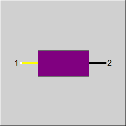
Line connections |
|
|
|
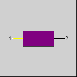
1 |
Actual value - process value |
|
|
2 |
Controlled value |
|
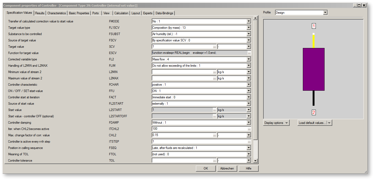
The colour indicates the type of activation of the controller (depending upon the flag FACT):
Dark purple: the controller starts immediately
Red: delayed start after 20, 30, 40 or 50 iterations
Pink: delayed start after 100 iterations
White: the controller is disabled
General User Input Values Characteristic Lines Physics Used Displays Example
Component 39 is the simplest controller in EBSILON®Professional. It differs from component 12 by not having a connection for the target value. For this reason, component 39 can be used only when the target value is constant. Details of controlling are described in Component 12.
A start value has to be specified for the controlled value, either internally as the specification value or externally via the component 33 (start value).
The start value should be at least in the order of magnitude of the expected value and not several powers of ten off. The recommended procedure is to get the model running without a controller first, then you will get suitable start values.
Component 39 can also be used for simple optimization tasks. To do this, the field SCV (scheduled value) is left blank. The controller then assumes that this value should be as high as possible. However, this feature functions only when the defaults are selected very carefully. The controller thereby requires (as normal) a monotonous relationship between the actual value and the correction value. The controlling stops when this monotony is violated. Therefore, basically one can find only the next local maximum. This feature is implemented as follows: starting from the 11th iteration step, the scheduled value is set to the (1+CHL3)-times of the actual value. If the actual value now increases, the scheduled value increases further. If the actual value reduces, the controller is disabled (and then remains so).
Controllers can be dampened even more. For this, three more damping levels ("very very high", "higher", "extremely high") have been introduced.
The sequence of the specification values in the input screen has been sorted. First are the specification values that relate to the reference value, and then the values that relate to the correction variable. Then follow general controller parameters like characteristic, activation, start value specification, and damping or limitation of change.
Decoupling of turn-on/-off feature and delayed start
The flag FACT served both to turn a controller on and off, and to specify a delayed start. In order to be able to better expand the setting options, this feature has been distributed to the two flags FACT and FFU.
The flag FACT is used to specify at which iteration step the controller is to start (at the earliest). FACT=0 means that the controller is to start as early as possible. The previous variants FACT=-1 and FACT=-2 for deactivating the controller with (-1) and without (-2) start value setting respectively have been marked as “deprecated“, but they are still operational for reasons of compatibility. However, it is recommended to use the new flag FFU for this purpose.
The flag FFU offers various variants for activating and deactivating controllers in different load cases. There are the following setting options:
• Controller active
- always: FFU=1
- only in design case: FFU=4 or -4
- only in off-design case: FFU=5 or -5
- never: FFU=0 or -1
• Controller not active (i.e. does not control) but sets its start value
- always: FFU=0
- only in design case: FFU=5
- only in off-design case: FFU=4
• Controller not active, without start value setting
- always: FFU=-1
- only in design case: FFU=-5
- only in off-design case: FFU=-4
Alternative start value in the case of deactivated controller:
The start value one wants to set with deactivated controller is not always suitable as start value in the case of activated controller (e.g. 0 kg/s). Previously one had to set different start values in different profiles then. There is an alternative start value L2STARTOFF (Component 39) and L3STARTOFF (Components 12 and 69) respectively for this. It is used when the controller is deactivated but is to set its start value. If no value is entered here, L2START and L3START respectively will be used also in the case of deactivated controller.
Compliance with limits:
The limits L2MIN/L2MAX (Component 39) and L3MIN/L3MAX (Component 12, Component 69) respectively were not strictly adhered to, but only caused the controller to be deactivated when the respective limit was exceeded. This mainly served to prevent a drifting off in the course of the iteration. For the final result, however, this behaviour is unsatisfactory as the precise achieved value depends on the behaviour of the iteration.
For this reason, the limits are strictly complied with. For reasons of compatibility, however, it is possible to switch back to the old behaviour via the flag FLIM. For this, FLIM has to be set to 0 (“Shut off controller after limit was exceeded“). The standard setting is FLIM=1 (“Stop at limit“).
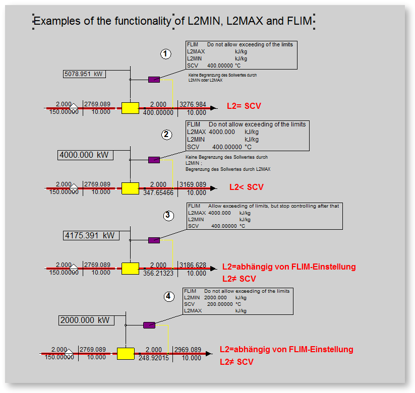
Functionality of the limits
The limits L3MIN/L3MAX (Component 12, Component 69) and L2MIN/L2MAX (Component 39) only become effective if numerical values are specified for them.
If that is the case, the flag FLIM checks according to the specification with
FLIM=0: the controller is switched off after the limit L3MIN/L3MAX is fallen below / transgressed
or with
FLIM=1: the controller stops on the limit L3MIN/L3MAX.
Deactivation of warnings:
A warning is issued by default when the controller cannot achieve its target value. In some cases, however, this is unnecessary, e.g. when, in the case of an injection, the inlet temperature is already below the set point temperature. In such cases it is possible to shut off the warning with the flag FWARN.
The flag FWARNOFF allows to activate or deactivate warnings for deactivated controllers. Here it is checked if the start value (in the case of component 69 also the off-value L3OFF) is within the range of validity.
Start Value Transfer In controllers (FMODE)
(Components 12, 39, and 69) it is possible to take over the result for the control variable as start value for the next calculation. As there is a certain analogy with respect to the transfer of the reference values for off-design calculations here, the flag for this has been named FMODE as well. The following settings exist:
The transferred value is written onto the specification values L2START and L2STARTOFF. However, it only has an impact if FL2START is set to “internal start value specification“. Also, the transfer only takes place if a value was entered into L2START respectively before. If the field has been set to the “empty”, the field will remain empty. When adding new controllers, FMODE=1 will be set by default. This is consistent with the previous behaviour. In a good modeling, the final result should in fact not (or only slightly) depend on the start value, but a change of the start value may lead to convergence problems. An influence on the final result also arises from the interaction of controllers with threshold values and limit values if it depends on the convergence behaviour when a controller is activated and deactivated respectively.
Flag FWARN
In the controllers there is a flag FWARN that allows setting in which situations the controller is to output warnings. For this there is a new setting FWARN=3.
With this setting, a warning is only output if the controller has not reached its target but the control variable has not reached its limit value either.
This setting makes sense if reaching the limit value represents a “normal” condition, like e.g. in the case of an injection where a certain temperature is to be set downstream
of the injection. By the injection, however, only a reduction of the temperature can be effected. If the temperature is below this set point value, nothing needs to be injected.
FWARN=3 allows to set that in this case no warning is to be effected. The control variable of the controller then equals the lower limit value of 0 kg/s, and no warning is output
if the set point value of the temperature has not been reached.
It is possible to output an error message instead of a warning with the setting FWARN=4.
FWARN=5 allows to individually program in a Kernel expression EWARN under which circumstances a comment, a warning or an error message is to be output.
Set Point Specification via Kernel Expressions
For the controllers that have the option for an internal set point specification (target value or scheduled value, Components 39 and 69) a Kernel expression ESCV can be used as an alternative to the specification value SCV. The control is affected via the flag FSCV:
• FSCV=0: the specification value SCV is used as set point value
• FSCV=1: (only for Component 69)
• FSCV=2: the set point value is determined from the Kernel expression ESCV.
Please note: as the set point value is usually a variable with units and – in contrast to the simple specification value – no automatic unit conversion can be carried out in the case of Kernel expressions, the value must be calculated in standard Ebsilon units.
Control Precision
For the solution of an equation system, Ebsilon continues the iteration as long as the changes from one iteration step to the next are smaller than the specified iteration precision.
Here the termination of the iteration is independent of to what extent the controllers have reached their set point value. Only a warning will be output if the deviation between actual value and set point value is too great.
In the case of strongly damped controllers in particular, the change from one iteration step to the next is relatively small, so that the convergence criterion is already fulfilled although the control target has not been achieved yet. In these cases it would be desirable if the iteration were continued for another couple of steps in order to get closer to the specified target.
It was therefore created the possibility to prevent a termination of the iteration in the case of too great a deviation from the set point value has been created.
Inversely, there are also cases where the adjustment of an unimportant variable requires very many iteration steps and thus increases the computing time for the entire model. In such cases it is desirable to be able to carry out the control with a greater fuzziness.
This option is available with the specification value TOL (for all controllers).
The specification value TOL is used for setting the control precision in both cases. Which one of the two cases is desired is set via the flag FTOL:
FTOL=1 (“TOL=lower bound“) serves to accelerate the control by means of a greater fuzziness. In this case, the controller terminates the control if the relative deviation between actual value and set point value falls below the bound TOL.
FTOL=2 (“TOL=upper bound“) prevents the termination of the iteration as long as the relative deviation between actual value and set point value transgresses the bound TOL. However, this does not apply if the correction variable has reached its lower or upper bound. As the controller does not continue operating in this case, carrying out further iteration steps does not make sense.
For analyzing the convergence behaviour, in the case FTOL=2 you can see in the result value ITNOTCONV up to which iteration step the controller has prevented a termination of the iteration. This allows to systematically find out the controllers that are responsible for a deterioration of the convergence behaviour and to improve their settings if necessary.
FTOL=0 is the default setting.
As in the case of controllers in Ebsilon the change of the actuating variable is effected via a change factor, controllers previously could not be operated in such a way that the actuating variable was able to change its algebraic sign. To enable this, there is now a specification value CZP that serves to shift the zero point of the controller internally. Shifting is effected in positive direction. If e.g. “100“ is entered, -100 will be mapped onto 0 and it will also be possible to control beyond 0 in the range >-100.
With great values of CZP, the internal actuating variable will become great accordingly so that this way, in the case of similar relative changes, the absolute change of the actuating variable will become very great too. This may lead to convergence problems. In this case, it is recommended to decrease the maximum change factor (CHL2respectively), and that from the beginning ( ITCHL2 = 0 respectively).
Previously, only fixed values could be entered as range limits for the actuating variable. Now it is possible to use a Kernel expression as the limit. To do so, the corresponding flag (FL2MIN and FL2MAX respectively for Components 12 and 69) has to be set to “Kernel expression“, and an EbsScript that calculates the corresponding limit has to be created in EL2MIN and EL2MAX respectively for Components 12 and 69.
This feature was needed for the variation of the steam inlet pressure for a preheater in order to achieve a certain feed water outlet temperature. Without limitation, the controller decreased the pressure so far that the saturated water temperature dropped below the feed water inlet temperature and no condensation was possible anymore. A fixed limit, however, was not possible either as the feed water inlet temperature is not known in advance but only appears in the course of the calculation. For instance, the following Kernel expression allows to set the lower pressure limit to a reasonable value in each iteration step:
function evalexpr:REAL;
begin
evalexpr:=waterSteamTable(1006, Feedwater.T, 0.0);
end;
To a relative humidity of z. For example, to set 100% or super saturation, a controller is required.
In the previous handling with the function "air humidity (rel.)", It could happen after iteration course that the air was supersaturated, i. Water contained in the liquid phase. The reason for this was that even with supersaturated air, the relative humidity remained at the value of 100% and the controller had thus reached its set point.
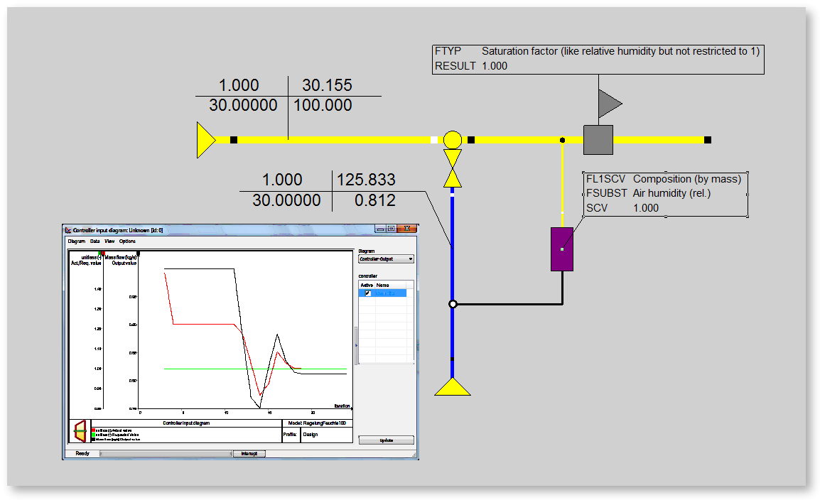
In order to allow a regulation to the saturation point (100%) or the setting of a certain super saturation, there is a function "saturation factor".
The saturation factor always refers to the maximum possible proportion of gaseous water. If the water content is higher, you get liquid water XH2OL. Humid air can only be considered approximately as an ideal gas. With increasing water content, the real proportion of gaseous water XH2OG decreases again. In the ideal approximation, the proportion of gaseous water would then simply remain constant, no matter how much liquid water would add to it. In reality, that's probably not the case
and therefore with supersaturated air:
XH2OG> X_SAT = f (p, t (air outlet line))
For values up to 100%, the results of the "Saturation factor" function are the same as those of the "Humidity (rel.)" Function.
Definition Saturation factor for "saturated air" 0 - 100%: The result values agree with the results of the "relative humidity" function.
Definition saturation factor for "supersaturated air"> 100% = corresponds to the ratio: total water content (XH2O) / maximum possible gaseous water content
(Water vapour saturation concentration x_sat = f (p, t (air, port 2))
Example: Application of saturation factor:
In the example circuit, the saturation factor is used for controlling the relative humidity. You can see in the controller input diagram that the red curve is above and below 1
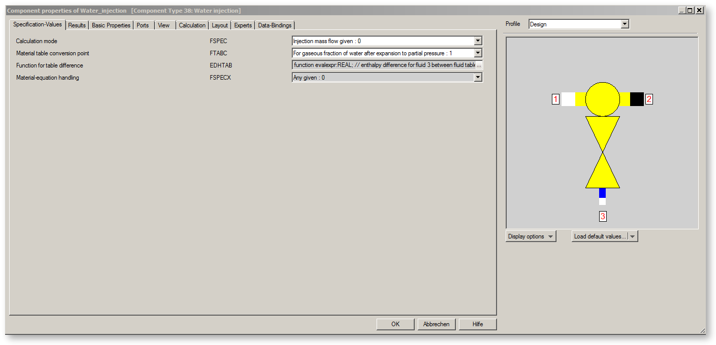
Specification-Values "Water injection"
Specification-Values "Controller 39"
|
Controller Main Attributes |
|
|
FFU |
Flag for ON / OFF / SET-start-value =0: OFF: Controller not active, but start value set in all load cases Note to -6/ - 7: In both cases, no controlling takes place. Actually the use of a controller is redundant in this case as the same |
|
FCHAR |
Flag for controller characteristics =1: Positive (i.e. an increase in the correction value causes an increase of the actual value) =-1: Negative (i.e. an increase in the correction value causes a lowering of the actual value) |
|
Process Variable |
|
|
FL1SCV |
Switch for comparison type between L1 (target value) and SCV (process value)
Here you will find a table for the values of FL1LSCV and the physical values used for each of the three connections. |
|
FSUBST |
Value to be controlled (active with FL1SCV=composition) |
|
Controller Output |
|
|
FL2 |
Flag for controlled variable type =1: Pressure |
|
FLIM |
Flag for Handling of L2MIN and L2MAX =0: Shut controller off after limit was exceeded =1: Stop at limit, |
|
FL2MIN |
Source of minimum value of controlled variable =0:Specification value L2MIN |
|
L2MIN |
Minimum value controlled variable |
|
EL2MIN |
Function for minimum value |
|
FL2MAX |
Source of maximum value of controlled variable =0:Specification value L2MAX |
|
L2MAX |
Maximum value controlled variable |
|
EL2MAX |
Function for maximum value |
|
FL2START |
Flag for the type of start value default =0: internal default through the specification value L2START =1: external (Stricter plausibility checks:, There will be error messages if |
|
L2START |
Start value of controlled variable (if FL2START=0) |
|
L2STARTOFF |
Alternative start value with FFU=0 (optional) |
|
Target value |
|
|
FSCV |
Source of target value
=0: Specification value SCV |
|
SCV |
target value |
|
ESCV |
Function for target value
function evalexpr:REAL;
begin
|
|
Additional Attributes |
|
|
FACT |
Number of iterations after which the controller is activated =0: immediately |
|
FDAMP |
Controller damping |
|
ITCHL2 |
Number of iterations after which the change factor becomes active (default value: 100) |
|
CHL2 |
Maximum change factor of corrected value (set as constant 0.15 till ITCHL2 is reached, after ITCHL2 according to the default between the limits: 0 < CHL3 <= 0.15) |
|
CZP |
Controller zero point |
|
STOPGRAD |
Stop controlling if gradient is less than |
|
ITSTEP |
Controller is active every n-th step (default value: 1) |
|
FSEQ |
Flag to define the position in calling sequence =0: Parallel to other components =1: Late, after fluids are recalculated |
|
FSTOP |
Stop behaviour if controller has not started =0: Do not stop iteration before controller has started |
|
FTOL |
Flag for meaning of TOL = 0: not used |
|
TOL |
Controller tolerance |
|
FSTOP |
Switch behaviour in achieving convergence =0: Do not stop iteration before controller has started =1: Stop in Case of convergency even if controller has not started |
| FMODE |
Flag for transfer of calculated value of controlled variable to start value =0 : After calculation in design mode |
|
Notification Options |
|
| FWARN |
Notification in case of missed target
=0: Not notification |
|
EWARN |
Function for notification
function evalexpr:REAL;
var target,actual,correction,errorlevel:real;
diff:real;
begin
target:=keGetInternal("TARGET");
actual:=keGetInternal("ACTUAL");
correction:=keGetInternal("CORRECTION");
errorlevel:=keGetInternal("ERRORLEVEL");
if (abs(target)>0) then begin //use relative deviation
diff:=abs(actual-target)/target;
end else begin
diff:=abs(actual-target);
end;
if (diff > errorlevel) then begin
evalexpr := 3; //Error
end else if (diff > 0.1*errorlevel) then begin
evalexpr := 2; //Warning
end else if (diff > 0.01*errorlevel) then begin
evalexpr := 1; //Comment
end;
|
|
FWARNOFF |
Plausibility check in case of inactive controller =0: No warning if range (L2MIN to L2MAX) is exceeded =1: Warning if range (L2MIN to L2MAX) is exceeded |
Generally, all inputs that are visible are required. But, often default values are provided.
For more information on colour of the input fields and their descriptions see Edit Component\Specification values
For more information on design vs. off-design and nominal values see General\Accept Nominal values
Information on the controller's result values can be found here.
CCHL2 - correction factor for CHL2
This characteristic enables one to change the maximum change factor CHL2 continuously in the course of the iteration (ITCHL2 enables an abrupt change in the iteration step ITCHL2). Normally, one will be able to narrow down the permissible deviation at the end of the iteration, in order to achieve a faster convergence.
x-value: Iteration step
y-value: Correction factor (CHL2 used = default value CHL2 * y-value)
With component 39 an outlet can be modelled with the help of a self-learning characteristic, which reaches the scheduled value SCV at the connection, from where the input is coming.
|
relative scheduled-actual value difference |
||
|
(Scheduled value-actual value) Si = --------------------------------------------- Scheduled value |
||
|
relative change of the correction value Ki |
||
|
| f(new) - f(old) | Ki= | ------------------------ | | f(old) | |
||
|
Change gradient |
||
|
Ki GRi = ----- Si |
||
The controller has got a "self-learning" characteristic i.e. the best possible changing of the correction value of the following iteration step is taken from the analysis of the controlling success of the last iteration steps. Therefore, the change gradient is used, which has been defined before. The change gradient is a measure of the relative changing of the correction value as a function of the relative variance difference. A change gradient GRi=1.0 results in a relative variance difference of, for instance, 5% to a changing of the correction value of even this 5%. The change gradient set to GRi=0.5 results from this supposed variance difference to a changing of the correction value of 2.5 %.
The gradient calculated from the last two steps is used to determine a new correction value as per the following table.
|
Correction value |
||
|
Df = f * GRi * Si f(new) = f(old) * (1.0 + Df) * FCHAR |
||
The change gradient has the following limits:
During the iteration steps 1 to 10, GRi will be set as follows:
from iteration 1 to 5: GRi = 0.95, and
from iteration 6 to 10: GRi = 0.90 .
Starting from iteration 11, the gradient GRi is calculated by interpreting the controlling success achieved.
The user must define the maximum and the minimum values for the GRi by using FDAMP (see list).
The value f(new) is bound via a sensitivity according to following regulations.
- If Ki is less than CHL2, f(new) is not considered,
- If Ki is higher than or equal to CHL2, f(new) is according to the following relationships:
|
f(new)=f(old)*(1 +/- CHL2) positive sign, if f(new) >= f(old) negative sign, if f(new) < f(old) |
||
The following rules apply to the determination of CHL2:
 |
Display Option 1 |
Click here >> Component 39 Demo << to load an example.