

|
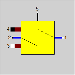
Line connections |
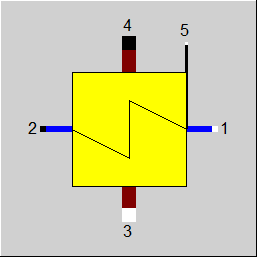 |
|
|
1 |
Primary side inlet (cold stream, inside the tubes) |
|
|
2 |
Primary side outlet (cold stream, inside the tubes) |
|
|
3 |
Secondary side inlet (hot stream, outside the tubes) |
|
|
4 |
Secondary side outlet (hot stream, outside the tubes) |
|
|
5 |
Control inlet for KAN- Design Heat Transfer Capability (as H) |
|
General User Input Values Characteristic Lines Physics Used Displays Example
This component models heat exchangers with phase transitions considering various heat transfer coefficients in the individual zones.
Before component 124, there were only two components in Ebsilon that support phase transitions:
Component 10: (Feed water preheater / heating condenser), where desuperheating zone and condensation zone are considered variably when using Rabek’s method.
This component, however, only allows to display one phase transition:
Component 71 (Once-through boiler), four cases with phase transition are implemented:
As phase transitions can occur both on the cold and on the hot side, there are 16 possible combinations altogether (cf. Fig.)
Calculation based on numerical solution:
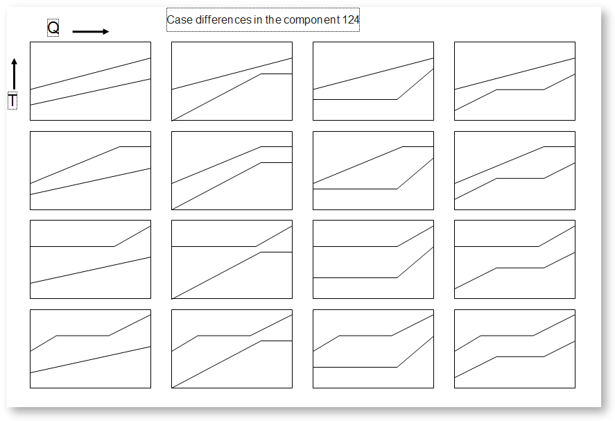
The range valid in the design case is set by means of the flag FTYPHX (“Type of heat exchanger“). To date, you can choose from:
0: General heat exchanger
1: Economizer
2: Evaporator
3: Superheated
The component 124 has been expanded to include a new calculation mode. This mode can be switched on with the new flag FALG = 0 / FALG = 1.
When FALG=0 the component 124 calculates the heat exchange based on an analytical solution, as before, where the K-number is calculated from the individual alpha numbers.
At FALG=1, by contrast, the heat exchanger is numerically solved in the direction of the flow direction of the working fluids.
The number of elements is set by means of the parameter NFLOW. Then a numerical solution of the heat exchange is sought, in analogy to Component 126.
To do so, the combined analytical and numerical procedure from Component 126 is applied. The difference to Component 126 consists in the fact that Component 124 only determines a steady-state solution. The result of the calculation depends on the number of the numerical elements (NFLOW) and the selection of the numerical scheme (FNUMSC). Compared to the analytical solution, the numerical solution has the advantage that it yields more precise solutions especially in the case of a strong non-linear dependency between the enthalpy and the temperature of the fluid (curvature of the lines in the QT diagram).
Convergence-Tuning:
Unfortunately, the convergence of the numerical solution cannot be guaranteed in all cases. In this case, it is recommended to change the number of points NFLOW or the numeric schema FNUMSC. The calculation with central differences (FNUMSC=1) is more accurate and therefore also the default setting.
However, it can lead to numerical problems, especially in the case of widely differing mass flows. In this case, a switch to the upwind method (FNUMSC=0) is recommended.
The mode"General heat exchanger" allows to cover Case 1, where a phase transition takes place neither on the cold nor on the hot side, with this component as well. This case can also be represented with other heat exchangers, but for the sake of completeness it is represented here too.
The flag FSPECD specifies in which way the design is effected. You can choose from
0: the specification of the effectiveness in the specification value EFF,
1: the specification of the lower terminal temperature difference in the specification value DTN, (see Heat Exchanger General Notes )
2: the specification of the upper terminal temperature difference in the specification value DTN, (see Heat Exchanger General Notes )
3: the specification of the outlet temperature of the hot stream in the specification value DTN,
4: the specification of both temperatures of the hot stream and a temperature of the cold stream on the respective lines, or
5: the specification of both temperatures of the cold stream and a temperature of the hot stream on the respective lines.
In either case the result of the design calculation is the nominal value for k*A, KAN.
As the component is to support phase transitions in off-design mode, specifying the alpha numbers and exponents for all phase ranges makes sense.
There are two identification modes (FIDENT=2) and (FIDENT=4): T2-specification and T4-specification. In these modes, in the off-design case, one does not work with the KAN and the corresponding scaling laws, but instead calculates k*A in such a way that the result is the desired temperature. In the identification mode, it is not necessary to differentiate between an Economizer, Evaporator, Superheated or general heat-exchanger.
The component can be deactivated with the switch FFU. In that case, heat is no longer exchanged, but pressure losses are still taken into account.
Heat losses DQLR can defined by means of a loss factor.
For this heat exchanger, it is possible, to specify the pressure externally (P2/P4).
It is also possible to use the flag FVOL to determine whether the off-design calculation of the pressure drop shall consider only the mass-flow (approximation for incompressible fluids) or mass
and volume flow.
Pinch point violations in the case of heat exchangers
In reality, heat can only be transferred from a warmer to a colder medium. This must be fulfilled not only at the end points, but also at every intermediate point of the heat exchanger.
In the numerical solution, these conditions are automatically fulfilled, as one intermediate point is calculated after the other. However, the prerequisite is that the number of intermediate points is large enough so that the specific heat within a cell can be regarded as constant.
With an analytical solution that only considers the end points, however, there may be places in the heat exchanger where this condition is violated ("pinch point violation"), namely when the specific heat is not constant (curved lines in the QT diagram), and especially at phase transitions. For this reason, a separate examination for pinch point violations must be carried out in the analytical solution after the calculation.
In the design case, however, it can happen that temperature specifications are set in such a way that they cannot be achieved at all without a pinch point violation. In this case, of course, the numerical method cannot find a solution and a corresponding error message is issued.
As the temperature remains constant during evaporation or condensation despite the supply or removal of heat, there are cases in which heat transfer is not physically possible despite a harmonious overall balance. In this case, the amount of heat transferred is reduced as far as physically possible, whereby the minimum pinch point can be set in a PINPMIN default value. This results in a correspondingly reduced KA.
The user is informed of this by the warning message ("KA reduced to avoid pinchpoint violation") and can then adjust the partial load characteristic curve or the partial load exponent for KA accordingly so that the warning no longer occurs. In any case, a physically possible result is obtained.
At the end of the calculation, there is also a check to see whether there is a pinch point violation due to the curved course of Q(T) (caused by significant changes in cp depending on the temperature). This can be understood by dividing the heat exchanger into individual sections. This can occur, for example, if the cp on the hot side is significantly lower at the inlet than at the outlet (e.g. with steam that has a cp of around 2 kJ/kgK at high superheat, but more than 5 just above the boiling line). This means that this steam provides more heat at a lower temperature level than at a high temperature level. With correspondingly low gradients, this can be a limitation for the possible heat transfer.
The QT diagrams take into account the non-linearity (curvature of the curves) in areas without phase changes.
The threshold value TOLXECO determines the value up to which evaporation in the Eco is tolerated. If the vapor content downstream of Eco is greater than the threshold, a warning message is issued; if it is greater than twice this threshold, an error message is issued.
The deprecated flag FSPEC has been replaced with three flags:
Note:
When loading a model that was created with Release 11 (or older), the corresponding values for FTYPHX, FSPECD, and FIDENT are determined from the value of the flag FSPEC, and FSPEC is set to “void” (-999). The model then calculates in the previous mode. If required, however, the flag FSPEC can still be used as well. This is necessary so that the existing EbsScripts in which a switchover of FSPEC into an identification mode is carried out will continue working. If FSPEC is not “empty” (-999) but has a value of -4 or -5 (the old values for the identification modes), the new flag FIDENT will be ignored, and the component will behave according to the setting of FSPEC (this is indicated in a comment).
To remove ambiguity, the terms “primary side” and “secondary side” respectively have been replaced by “cold side” and “warm side” in the input screens. The cold side is the flow from Pin 1 to Pin 2 that is heated. The warm side is the flow from Pin 3 to Pin 4 that gives off the heat.
Effectiveness Method
See Heat Exchangers General Information Effectiveness Method
Design in the Case of Concurrent Flow
In the heat exchanger (Components 124) it is possible to carry out a design via the upper and lower terminal temperature difference, (see Heat Exchanger General Notes ) also in the case of concurrent flow (FFLOW=1).
If both inlet temperatures are specified, the upper terminal temperature difference can only be determined iteratively. Usually this is no problem. If convergence problems occur in more
complex models, another design mode will have to be used.
Note for heat exchanger type evaporator:
For an evaporator, the outlet temperature is defined by the pressure. Thus in this case one degree of freedom less is available. Therefore specifying the upper terminal temperature difference (in counter current flow) was not possible for the evaporator.
It is possible also in the case of an evaporator to specify the upper (in counter current flow) and lower (in concurrent flow) terminal temperature difference respectively for the design. In this case the component then calculates the inlet temperature of the warm fluid. The reason is that with the setting “Evaporator” (2) superheated steam is accepted at the outlet as well, and therefore the outlet temperature is unknown.
Flag FDQLR
You can use the FDQLR flag to define how DQLR (factor for modeling heat losses) should be interpreted.
Specification of the surface in the design case
In the design case, this component allows to specify the surface area of the heat transfer surface too. To do so, the flag FSPECD has to be set to the value 9 and the surface area has to be entered in the specification value AN. For all other settings of FSPECD, AN will be calculated. As AN has been calculated during the design at all times, this value was located among the blue nominal values. Because a specification in the design case is possible, the value has been moved to the black specification values.
Optional use of KAN or AN for off-design calculations
According to the design calculation, the values KAN, KN, and AN are consistent to each other (KAN = KN * AN). If one of these values is changed manually, the consistency will get lost. Previously, the user was informed about this by means of a warning. The component then considered the values KN and AN as correct and ignored KAN. As KAN, however, is often adjusted manually or by means of an EbsScript in other heat exchangers in order to simulate fouling of the heat exchanger, this has been enabled for Component 124 as well. To do so, there is a flag FKAN that specifies whether AN (at FKAN = 0) or KAN (at FKAN = 1) is to be considered as reliable in the case of inconsistent values. The warning on the inconsistency between KAN and AN has been downgraded to a comment because otherwise both values would always have to be changed simultaneously. Moreover, the heat transfer coefficient K is displayed as result value.
Adaptation polynomial / Kernel expression
In analogy to Component 61, Component 124 also allows to use an adaptation polynomial and a Kernel expression respectively. Here the activation is effected via the flag FADAPT too. Please note: the flag existed in this component before but it was functionless.
Distribution in the identification mode
The distribution of the surfaces and the transferred heat quantities to economizer, evaporator, and superheated is also displayed in identification mode (FIDENT > 0) in the result values.
Heat Transfer Coefficients
Component 124 offers the option of specifying different alpha numbers and exponents for the individual zones. With the numerical solution, you can choose to work with constant or range-dependent alpha numbers. For this reason, the FTYPHX switch distinguishes between
If FTYPHX = 1 (Eco), 2 (evaporator) or 3 (superheater) is set for the numerical algorithm, the alpha numbers are used zone-specifically, as is the case with FTYPHX=4, as is also the case with the analytical solution.
The use of zone-specific alpha numbers (FTYPHX>0) is restricted to pure substances (e.g. water vapor, user-defined two-phase fluid).
When using mixtures (e.g. FDBR, universal fluid), the values
are provided for such fluids. If a component of the mixture undergoes a phase change with FTYPHX>0 within the heat exchanger (numerical solution FALG=1), these default values are used instead of AL12N, EX12, AL34N, EX34. This may be the case, for example, when the water content in the gas condenses.
As an alternative to specifying the nominal values and exponents of the heat transfer coefficients, the heat transfer coefficients within the heat exchanger (numerical solution FALG=1) can be calculated using kernel expressions
can be calculated. To distinguish between the specification of the nominal values, exponents and the kernel expressions, the switches
are provided.
Useful values for alpha numbers for the different fluid combinations can be found in the standard data sets of component 61.
Pressure loss distribution among areas
At FALG=1 (numerical calculation mode) for pure fluids at flow path 1->2 the overall pressure drop DP12 can be distributed to the area specific pressure drops DP12ECO, DP12EVA, DP12SUP. The distribution appears depending on the area parts occupied by the corresponding area as well as on the specific vloume of the fluid on the inlet of the corresponding area.
The nominal value for specific volume is computed at Design conditions as
V1N = (V12_INL * AECO + V12_LIQ * AEVA + V12_GAS * ASUP) / AN
Here are
V12_INL - the specific volume value at the inlet 1
V12_LIQ, V12_GAS - the specific volume values of the saturated liquid and gas on the flow path 12.
For the determination of the last two values the mean pressure value (P1+P2)/2 is used
Finally the area specific pressure drops are computed as
DP12ECO = DP12N * (M1/M1N) * (M1/M1N) * FL12 * V12_INL * AECO / (AN * V1N)
DP12EVA = DP12N * (M1/M1N) * (M1/M1N) * FL12 * V12_LIQ * AEVA / (AN * V1N)
DP12SUP = DP12N * (M1/M1N) * (M1/M1N) * FL12 * V12_GAS * ASUP / (AN * V1N)
At Design FL12 = 1
At Off-Design FL12 = (V12_INL * AECO + V12_LIQ * AEVA + V12_GAS * ASUP) / (AN * V1N)
Notice that the values AECO, AEVA, ASUP at Off-Design differ from those at Design conditions. Thus, FL12 deviates from 1.
For more information on how this heat exchangers compares to other heat exchangers, see Heat Exchanger General Notes
|
FMODE |
Calculation mode (design / off design) =0: GLOBAL =1: local off-design (i.e. always off-design mode, even when a design calculation has been done globally) =2: special local off-design (special case for compatibility with the earlier Ebsilon-versions, should not be used in newer models, because the results = -1: local design (i.e. always design mode, even when a off-design calculation has been done globally) |
|
FTYPHX |
Type of heat exchanger = 0: General heat exchanger |
|
FSPECD |
Calculation method in design-case
= 0: Specification of the effectiveness (ratio of transferred heat to the theoretical maximum at infinite transfer surface) in the specification value EFF |
|
FIDENT |
Activation of a component identification mode (only in off-design)
(FIDENT serves to activate a component identification mode, i.e. the respective condition of the component is determined on the basis of temperature specifications) = 0: No identification mode In the design case, variant FIDENT=2 is identical with FSPECD=5 and FIDENT=4 with FSPECD=4. In order to prevent contradictory specifications, the flag FIDENT is therefore only used in off-design for this component. Please note: the peculiarity for these components is that in the design case identification (namely the calculation of KAN from temperature specifications) takes place by default. For other components this is not the case. |
|
EFF |
Effectiveness |
|
DTN |
Temperature specification (nom.) According to FSPECD |
|
AN |
Heating surface (nominal) |
| FVOL |
Flag for considering the dependency of pressure loss on volume =0: no dependency on the specific volume DP/DPN = (M/MN)**2 =1: dependent on the specific volume DP/DPN = V/VN*(M/MN)**2 |
| FDPNUM |
Pressure loss handling in the numerical solution =0: Using the average fluid pressure between inlet and outlet |
|
FDP12RN |
Flag for handling pressure drop of stream 12 =1: calculated by DP12N = DP12RN (absolute) |
|
DP12RN |
Pressure drop 12 (nominal) [absolute or relative to P1] |
|
FDP34RN |
Flag for handling pressure drop of stream 34 =1: calculated by DP34N = DP34RN (absolute) |
|
DP34RN |
Pressure drop 34 (nominal) [absolute or relative to P3] |
|
FDQLR |
Heat loss handling =0: Constant (DQLR*QN in all load cases) |
|
DQLR |
Heat loss (relative) |
|
FFLOW |
Flag to specify the flow direction =0: Counter Current flow |
|
NROW |
Number of rows (for cross flow) |
|
NPASS |
Number of passes (for cross flow) |
|
FARR |
Flag to specify the arrangement of passes =0: Counter Current flow =1: Concurrent flow |
|
FFU |
Switch On / Off =0: Heat exchanger OFF (no heat transfer, but pressure losses) =1: Heat exchanger ON (active) |
|
AL12N |
Heat transfer coefficient cold side (nominal) |
|
EX12 |
Flow rate exponent of AL12 |
|
AL34N |
Heat transfer coefficient hot side (nominal) |
|
EX34 |
Flow rate exponent of AL34 |
| DAL34DT | Additional partial load gradient for AL34 - see component 61 The temperature dependency of AL34 can thus be influenced - default value up to release 16: 0.0005 |
| AL34RN | Hot side radiation transfer coefficient (nominal) |
|
AL12ECON |
Heat transfer coefficient economizer cold side (nominal) |
|
EX12ECO |
Flow rate exponent of AL12ECO |
|
AL34ECON |
Heat transfer coefficient economizer hot side (nominal) |
|
EX34ECO |
Flow rate exponent of AL34ECO |
|
AL12EVAN |
Heat transfer coefficient evaporator cold side (nominal) |
|
EX12EVA |
Flow rate exponent of AL12EVA |
|
AL34EVAN |
Heat transfer coefficient evaporator hot side (nominal) |
|
EX34EVA |
Flow rate exponent of AL34EVA |
|
AL12SUPN |
Heat transfer coefficient superheated cold side (nominal) |
|
EX12SUP |
Flow rate exponent of AL12SUP |
|
AL34SUPN |
Heat transfer coefficient superheated hot side (nominal) |
|
EX34SUP |
Flow rate exponent of AL34SUP |
|
AL34RN |
hot side radiation transfer coefficient (nominal) |
|
FOUL |
Fouling factor |
|
FSPECK |
Flag for k calculation in off-design =0: like component 61 (default value) |
|
FVALKA |
Validation of k*A (only in off-design) =0: KAN used without validation |
|
IPS |
Index for pseudo measurement point |
|
FADAPT |
Flag for using the adaptation polynomial ADAPT / adaptation function EADAPT =0: Not used and not evaluated =1: Correction for k*A [KA = KAN * K/KN * polynomial] =2: Calculation of k*A [KA = KAN * polynomial] =1000: Not used but ADAPT evaluated as RADAPT (Reduction of the computing time) =-1: Correction for k*A [KA = KAN * K/KN* adaptation function] =-2: Calculation of k*A [KA = KAN * adaptation function ] =-1000: Not used but EADAPT evaluated as RADAPT (Reduction of the computing time) |
|
EADAPT |
Adaptation function for KA function evalexpr:REAL; |
|
TOLXECO |
Tolerance for evaporation in an economizer. If the steam content X at the economizer outlet is > TOLXECO, a warning message is issued. If it is > 2*TOLXECO, an error message is issued. |
|
PINPMIN |
Minimum value for the pinch point (KA is reduced automatically if the pinch point would fall below this value) |
|
FSPEC (deprecated) |
Flag for the mode of operation and temperature definition = -999: unused (FSPECD and FIDENT used instead) old values: =0: General heat exchanger; Effectiveness method =1: General heat exchanger; DTN = lower terminal temperature difference =2: General heat exchanger; DTN = upper terminal temperature difference =3: General heat exchanger; DTN = T4 =4: General heat exchanger; user specifies T3, T4 and T1 or T2 =5: General heat exchanger; user specifies T1, T2 and T3 or T4
=10: Economizer; Effectiveness method =11: Economizer; DTN = lower terminal temperature difference =12: Economizer; DTN = upper terminal temperature difference =13: Economizer; DTN = T4 =14: Economizer; user specifies T3, T4 and T1 or T2 =15: Economizer; user specifies T1, T2 and T3 or T4
=20: Evaporator; Effectiveness method =21: Evaporator; DTN = lower terminal temperature difference =22: Evaporator; DTN = upper terminal temperature difference =23: Evaporator; DTN = T4 =24: Evaporator; user specifies T3, T4 and T1 or T2 =25: Evaporator; user specifies T1, T2 and T3 or T4
=30: Superheated; Effectiveness method =31: Superheated; DTN = lower terminal temperature difference =32: Superheated; DTN = upper terminal temperature difference =33: Superheated; DTN = T4 =34: Superheated; user specifies T3, T4 and T1 or T2 =35: Superheated; user specifies T1, T2 and T3 or T4
= -5: T2 given (also in off-design). Note: If this method is used in off-design, the mass and energy balances will be observed, but the heat exchanger will be resized. Use this method only when appropriate, such as for data reconciliation. This method could violate the second law of thermodynamics. = -4: T4 given (also in off-design). Note: If this method is used in off-design, the mass and energy balances will be observed, but the heat exchanger will be resized. Use this method only when appropriate, such as for data reconciliation. This method could violate the second law of thermodynamics. |
|
FSPECLAM |
Flag for specifying the lambda calculation (Yet possible no selection) =1: 1 |
|
FTYP |
Flag for specifying the type calculation (Yet possible no selection) =1: 1 |
|
FKAN |
Use KAN or AN use( in partial load )? =0: Use AN |
|
FALG |
Heat exchange calculation algorithm (steady state solution) |
|
NFLOW |
Number of points in flow direction (max. 100) 30 |
|
FNUMSC |
Numeric scheme =0: Upwind |
|
KAN |
Overall Heat transfer coefficient * Area (nominal) - Design Heat Transfer Capability |
|
KN |
Overall Heat transfer coefficient (nominal) |
|
QN |
Heat flow |
|
M1N |
Cold side mass flow (nominal) |
|
M3N |
Hot side mass flow (nominal) |
|
V1N |
Specific volume at point 1, inlet (nominal) |
|
V3N |
Specific volume at point 3, inlet (nominal) |
|
TM34N |
Medium flue gas temperature (nominal) |
|
P1N |
Pressure at point 1, inlet (nominal) |
|
P3N |
Pressure at point 3, inlet (nominal) |
|
ALAMN |
Conductivity of the material (nominal) |
|
T12N |
Average actual temperature of hot side (nominal) |
|
TMATN |
Heat exchanger material temperature (nominal) |
The parameters marked in blue are reference quantities for the off-design mode. The actual off-design values refer to these quantities in the equations used .
Generally, all inputs that are visible are required. But, often default values are provided.
For more information on colour of the input fields and their descriptions see Edit Component\Specification values
For more information on design vs. off-design and nominal values see General\Accept Nominal values
|
Q21 |
Heat given to cold side |
|
QT |
Transferred heat |
|
Q34 |
Heat delivered from hot side flow |
|
KA |
Overall heat transfer coefficient * Area = Q/DTM |
|
KAPH |
Overall heat transfer coefficient * Area = physical value |
|
K |
Overall heat transfer coefficient |
|
DTM |
Mean logarithmic temperature difference |
|
DTLO |
Lower terminal temperature difference |
|
DTUP |
Upper terminal temperature difference |
|
KACL |
KA calculated according to component-specific off design behaviour |
|
RPFHX |
Upper terminal temperature difference |
|
REFF |
Upper terminal temperature difference |
|
X2 |
Steam quality (X) at cold side outlet |
|
A |
Used heat exchange area |
|
AECO |
Heat exchange area economizer |
|
AEVA |
Heat exchange area evaporator |
|
ASUP |
Heat exchange area superheated |
|
QLT |
Total heat loss |
|
QLRT |
Relative total heat loss |
|
QLRECO |
Relative heat loss economizer |
|
QLREVA |
Relative heat loss evaporator |
|
QLRSUP |
Relative heat loss superheated |
|
DP12ECO |
Pressure loss of economizer (cold side) |
|
DP12EVA |
Pressure loss of evaporator (cold side) |
|
DP12SUP |
Pressure loss of superheated (cold side) |
|
DP12 |
Total pressure loss (cold side) |
|
DP34 |
Total pressure loss (hot side) |
|
CP12 |
Average specific heat capacity (cold side) |
|
CP34 |
Average specific heat capacity (hot side) |
|
HS1 |
Enthalpy of saturated water at inlet |
|
HS2 |
Enthalpy of saturated steam at outlet |
|
TS1 |
Temperature of saturated water at inlet |
|
TS2 |
Temperature of saturated steam at outlet |
|
QECO |
Exchanged heat, economizer |
|
QEVA |
Exchanged heat, evaporator |
|
QSUP |
Exchanged heat, superheated |
|
Q12IP |
Heat transfer to flow 12 up to intermediate point |
|
T12IP |
Temperature at flow 12 up to intermediate point |
|
DTIP |
Temperature difference between flow 34 and flow 12 at intermediate point |
|
RADAPT |
Result of ADAPT / EADAPT |
Specific heat capacity : CP12 / CP34
The mean specific heat capacity is displayed as result value on the cold side (CP12) and on the hot side (CP34).
The mean specific heat capacity results from the quotient of the enthalpy difference and the temperature difference.
If no temperature difference is present (e.g. in the two-phase range or when the heat exchanger is shut off), however, it is not possible to calculate this quotient. In this case, the specific heat capacity at the respective temperature is used, provided that it is defined. Otherwise the result value will remain blank.
Performance factor RPFHX
The quotient from the current value for k*A (result value KA) and the k*A expected in the respective load point due to the component physics and characteristic lines respectively (result value KACL) serves to assess the condition of a heat exchanger.
The quotient KA / KACL is displayed as result value RPFHX.
These result arrays are available:
|
Design case (Simulation flag: GLOBAL = design case and FMODE = GLOBAL) |
||
|
Off-design case (Simulation flag: GLOBAL = off-design or FMODE = local off-design) |
||
 |
Display Option 1 |
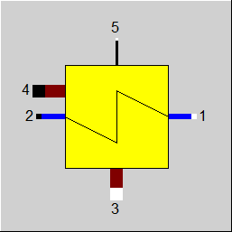 |
Display Option 2 |
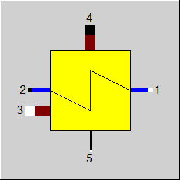 |
Display Option 3 |
 |
Display Option 4 |
Click here >> Component 124 Demo << to load an example.