
EBSILON®Professional Online Dokumentation


|
Anschlüsse |
|
|
|
1 |
Wasser-Eingang |
|
|
2 |
Wasserstoff-Ausgang |
|
|
3 |
Sauerstoff-Ausgang |
|
|
4 |
Elektrische Leistung Eingang |
|
|
5 |
Wasserspülung-Ausgang |
|
|
6 |
Heiz-Eingang |
|
|
7 |
Kühl-Ausgang |
|
|
8 |
Regel-Eingang |
|
|
9 |
Daten-Ausgang |
|
Allgemeines> Vorgabewerte Kennlinien Physick Ansichten Beiispiel
Bauteil 167 bildet eine Elektrolysezelle ab.
|
FTYPE |
Flag für den Brennstoffzellen-Elektrolyt-Typ =0: O-- Ionen-Transport (SOEC) =1: H+ Ionen-Transport (z. B. PEM), gesättigtes Gas an beiden Auslässen =2: OH- Ionen-Transport (z. B. AEC) |
|
CELLAREA |
Zellfläche |
|
NCELLSPERSTACK |
Anzahl der Zellen pro Stapel |
|
NSTACKS |
Anzahl der Stapel |
|
TEMP |
Betriebstemperatur |
|
FCURRENT |
Flag für aktuelle Zelleinstellungen: =0: Wert von CURRENT verwenden =1: Durchsatz über Anschluss 8 setzen |
|
CURRENT |
Zellstrom |
| PURGEFRAC | Reinigungsstrom-Anteil |
|
FLOSSES |
Flag für Methode für elektrische Verluste: =0: Kennlinie CUI für Referenz-Fluidkonzentration verwenden =1: Vorgabedaten für Ohmsche und Aktivierungs-Verluste verwenden |
|
AN_H2_REF |
Molare Anoden-H2-Referenz-Konzentration |
|
AN_H2O_REF |
Molare Anoden-H2O-Referenz-Konzentration |
|
CAT_O2_REF |
Molare Kathoden-O2-Referenz-Konzentration |
|
CAT_H2O_REF |
Molare Kathoden-HO2-Referenz-Konzentration |
|
T_REF |
Referenztemperatur |
|
P_REF |
Referenzdruck |
|
FOHMICLOSSES |
Flag für Berechnungsmodus Ohmsche Verluste: =0: Leitfähigkeit setzen =1: Gesamtdefinition =2: Detailllierte Layerdefinition |
|
SIGMA_I |
Ionen-Leitfähigkeit pro Fläche |
|
FSIGMA_I |
Flag für Definition Ionenleitfähigkeit: =0: Sigma=K/T*exp(-Ea/(RT)) =1: Sigma=K*exp(-Ea/(RT)) |
|
K_SIGMA_I |
Ionenleitfähigkeit K |
|
EAR_SIGMA_I |
Ionenleitfähigkeit Ea/R |
|
EL_D |
Elektrolyt-Dicke |
|
EL_FSIGMA_I |
Flag für Definition Elektrolyt-Ionenleitfähigkeit =0: Sigma=K/T*exp(-Ea/(RT)) =1: Sigma=K*exp(-Ea/(RT)) |
|
EL_K_SIGMA_I |
Elektrolyt-Ionenleitfähigkeit K |
|
EL_EAR_SIGMA_I |
Elektrolyt-Ionenleitfähigkeit Ea/R |
|
CAT_D |
Kathodendicke |
|
CAT_FSIGMA_E |
Flag für Definition Kathoden-Elektronenleitfähigkeit: =0: Sigma=K/T*exp(-Ea/(RT)) =1: Sigma=K*exp(-Ea/(RT)) |
|
CAT_K_SIGMA_E |
Kathoden-Elektronenleitfähigkeit K |
|
CAT_EAR_SIGMA_E |
Kathoden-Elektronenleitfähigkeit Ea/R |
|
AN_D |
Anodendicke |
|
AN_FSIGMA_E |
Flag für Definition Anoden-Elektronenleitfähigkeit: =0: Sigma=K/T*exp(-Ea/(RT)) =1: Sigma=K*exp(-Ea/(RT)) |
|
AN_K_SIGMA_E |
Anoden-Elektronenleitfähigkeit K |
|
AN_EAR_SIGMA_E |
Anoden-Elektronenleitfähigkeit Ea/R |
|
IC_D |
Verbindungsdicke |
|
IC_FSIGMA_E |
Flag für Definition Verbindungs-Elektronenleitfähigkeit =0: Sigma=K/T*exp(-Ea/(RT)) =1: Sigma=K*exp(-Ea/(RT)) |
|
IC_K_SIGMA_E |
Verbindungs-Elektronenleitfähigkeit K |
|
IC_EAR_SIGMA_E |
Verbindungs-Elektronenleitfähigkeit Ea/R |
|
FACTLOSS |
Flag für Berechnungsmodus Aktivierungsverluste =0: Keine Aktivierungsverluste =1: Butler-Volmer-Gleichung |
|
AN_ACT_K |
Anode K [Jref=yH2*yH2O*K*exp(-Ea/(R*T))] |
|
AN_ACT_EA |
Anode Ea [Jref=yH2*yH2O*K*exp(-Ea/(R*T))] |
|
CAT_ACT_K |
Kathode K [Jref=pow(yO2,0.25)*K*exp(-Ea/(R*T))] |
|
CAT_ACT_EA |
Kathode Ea [Jref=pow(yO2,0.25)*K*exp(-Ea/(R*T))] |
|
CDRAGH2O |
PEM Elektro-osmotischer Netto-Widerstandsbeiwert (nH2O/nH+) |
|
FXOH2 |
Flag für H2-Crossover Berechnungsmodus =0: Wert von XOH2 verwenden =1: Kennlinie CXOH2 verwenden =2: Ausdruck EXOH2 verwenden |
|
XOH2 |
H2-Crossover von produziertem H2 |
|
EXOH2 |
Ausdruck für H2-Crossover von produziertem H2 |
|
FXOO2 |
Flag für O2-Crossover Berechnungsmodus: =0: Wert von XOO2 verwenden =1: Kennlinie CXOO2 verwenden =2: Ausdruck EXOO2 verwenden |
|
XOO2 |
O2-Crossover von produziertem O2 |
|
EXOO2 |
Ausdruck für O2-Crossover von produziertem O2 |
|
FDEGRADATION |
Flag für Degradierungsmodus: =0: Keine Degradierung =1: Wert von AREAFRACTION verwenden =2: Kennlinie CDEGRADATION verwenden =3: Ausdruck EAREAFRACTION verwenden |
|
AREAFRACTION |
Anteil der aktiven Fläche |
|
EOHOURS |
Äquivalente Betriebsstunden |
|
EAREAFRACTION |
Ausdruck für den Anteil der aktiven Fläche |
Die blau markierten Parameter sind Bezugsgrößen für den Off-Design-Modus. Diese werden bei der Auslegungsberechnung von EBSILON®Professional errechnet und eingetragen.
Im Allgemeinen sind alle sichtbaren Eingaben erforderlich. Häufig werden jedoch Standardwerte angegeben.
Weitere Informationen zur Farbe der Eingabefelder und deren Beschreibungen finden Sie unter Komponenten bearbeiten\Vorgabewerte.
Weitere Informationen zu Auslegungs- vs. Nicht-Auslegungs- und Nennwerten finden Sie unter Allgemeine Einstellungen\Nominalwerte übernehmen.
|
NAME |
X |
Y |
|
CUI |
Strom |
Spannung |
|
CDEGRADATION |
Betriebsstunden |
Flächenanteil |
|
CXOH2 |
Stromdichte |
Anteil des produzierten H2 (Crossover-Anteil) |
|
CXOO2 |
Stromdichte |
Anteil des produzierten O2 (Crossover-Anteil) |
|
PEL |
Elektrische Leistung |
|
U |
Spannung |
|
I |
Stromstärke |
|
ENERGYCON |
Spezifischer Energieverbrauch pro kg H2 |
|
AREA |
Gesamtfläche |
|
ADEGRAD |
Degradierung der effektiven Fläche |
|
AREA_EFF |
Effekive Fläche |
|
NCELLS |
Gesamtzahl der Zellen |
|
PELCELL |
Zellleistung |
|
UCELL |
Zellspannung |
|
ICELL |
Zellstromstärke |
|
JCELL |
Zellstromdichte (auch auf Port 9 als Enthalpie) |
|
SIGMA_I_CELL |
Ionen-Leitfähigkeit pro Fläche |
Das thermodynamische Modell ähnelt dem der Brennstoffzelle (Komponente 163) in umgekehrter Richtung. Das Modell ist nulldimensional, d. . es gibt weder ein Temperatur- noch ein Konzentrationsprofil zwischen Ein- und Auslass. Die Temperatur wird als konstant angesehen und für die Konzentrationen wird ein Mittelwert zwischen Einlass und Auslass genommen.
Das Modell erlaubt verschiedene Detailstufen für die Strom-Spannungs-Kennlinie des Stacks:
- benutzerdefinierte Kurve
- Einstellung der Gesamtleitfähigkeit für 1/R1
- Einstellung der temperaturabhängigen Gesamtleitfähigkeit für 1/R1
- Einstellung der temperaturabhängigen Leitfähigkeiten für jede Schicht und Berechnung von R1
Emax wird mit der Nernst-Gleichung berechnet. Für die Reaktion
(Ox) a A + b B + ... <=> c C + d D + ... (Red)
kann das Potenzial E für eine Temperatur T wie folgt berechnet werden
Emax(T) = E0 - (RT)/(zF)*ln((aCc*aDd)/(aAa*aBb))
E0 = ΔG0/(RT)
| R1 | Gesamte ohmsche Verluste |
| A, B, C, D |
Komponente A,B,C,D in der Reaktion |
| a,b,c,d | Stöchiometrische Koeffizienten der Komponenten in der Reaktion |
| E0 | Bezugspotenzial |
| Emax(T) | Potential bei Temperatur T für gegebene Aktivitäten von A,B,C,D |
| aA, aB, aC, aD | Aktivitäten der Komponenten A,B,C,D |
| ΔG0 | Gibbs'sche freie Energie der Reaktion unter Referenzbedingungen (Aktivität=1, p=pref) |
| z | Elektronen, die an der Redoxreaktion beteiligt sind |
| F | Faraday Konstante |
| R | Gaskonstante |
| T |
Temperature |
Wenn FLOSSES auf den Kurvenmodus eingestellt ist, werden alle Verluste direkt aus der Kurve abgeleitet. Für eine gegebene Stromdichte wird eine Kurvensuche durchgeführt und über die Nernst-Gleichung wird Emax für die Referenzflüssigkeit berechnet. Die Differenz wird als die Verluste betrachtet, die bei den aktuellen Bedingungen anfallen.
Im Nicht-Kurvenmodus wird Emax um ohmsche Verluste, Aktivierungsverluste und Überkreuzungsverluste reduziert, falls gewünscht.
Die Aktivierungsverluste werden nach der Butler-Volmer-Gleichung für die Anoden- und Kathodenseite berechnet.
Die ohmschen Verluste werden entsprechend der Einstellung von FOHMICLOSSES berechnet. Wird temperaturabhängiges Verhalten gewählt, wird eine Arrhenius-Formulierung für die Leitfähigkeit verwendet.
Die Crossover-Verluste ermöglichen die Modellierung der Migration von H2 und O2 über den Elektrolyten. Zusätzlich kann für PEM ein Wasserwiderstandskoeffizient angegeben werden, der es erlaubt, die Migration von Wasser im elektrischen Feld über den Elektrolyten zu modellieren.
Die Degradation wird durch eine Verringerung der aktiven Stackfläche modelliert, was zu einer Erhöhung der Stromdichte und damit zu einer Erhöhung der Verluste führt. Die Verringerung der aktiven Fläche wird mit einer Kennlinie CDEGRADATION modelliert, die äquivalente Betriebsstunden gegenüber dem aktiven Flächenanteil modelliert.
Kurzweil, Dietlmeier, Elektrochemische Speicher, Springer Vieweg (2018)
|
H4 = Pel |
Elektrische Leistung |
|
P4 = U |
Spannunf |
|
M4 = 0 |
DC |
|
P1 = P2 = P3 = P5 |
|
|
M5 = m_purge |
purge |
|
M1 - M2 = m_O2 |
H2 Produktion (nur beim Typ SOFC) |
|
M3 - M2 = m_O2 - (m_H2+m_excess) |
O2 Produktiongleichgewicht |
|
M2 = m_H2 |
H2 Produktion (nur beim Typ PEM oder OH-) |
|
M1 = m_H2 + m_O2 + m_purge |
Wasserzufuhr (nur beim Typ PEM oder OH-) |
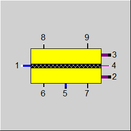 |
Ansicht1: Elektrolysezelle |
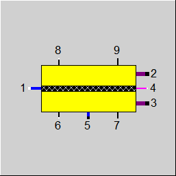 |
Ansicht2: Elektrolysezelle |
Hier klicken >> Component 167 Demo << um ein Beispielsmodell zu laden.