EBSILON®Professional Online Dokumentation


Allgemeines Vorgabewerte Kennlinien Physik Ansichten Beispiel
|
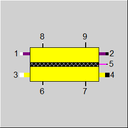
Anschlüsse |
|
|
|
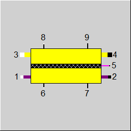
1 |
Brennstoffeingang |
|
|
2 |
Brennstoffausgang |
|
|
3 |
Oxidationsmittel-Eingang |
|
|
4 |
Oxidationsmittel-Ausgang |
|
|
5 |
Elektrische Leistung |
|
|
6 |
Heiz-Eingang |
|
|
7 |
Kühl-Ausgang |
|
|
8 |
Regel-Eingang |
|
|
9 |
Daten-Ausgang |
|
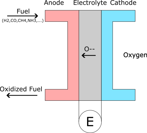
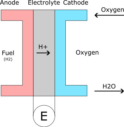
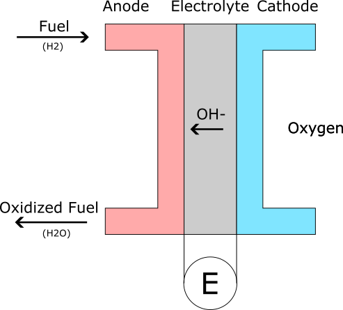
Die Komponente 163 stellt eine Brennstoffzelle dar. Derzeit sind drei verschiedene Ionentransporttypen implementiert: O-- , H+ and OH-
|
O-- |
e.g. SOFC |
|
|
H+ |
e.g. PEM |
|
|
OH- |
e.g. AFC |
|
|
FTYPE |
Flag für Typ der Brennstoffzelle: =0: O-- Ionen-Transport (SOFC) =1: H+ Ionen-Transport (e.g. PEM) =2: OH- Ionen-Transport (e.g. AFC) |
|
CELLAREA |
Zellfläche |
|
NCELLSPERSTACK |
Anzahl der Zellen pro Stapel |
|
NSTACKS |
Zahl der Stapel |
|
TEMP |
Betriebstemperatur |
|
FCURRENT |
Aktuelle Zelleinstellungen: =0: Wert von CURRENT verwenden =1: Duch Anschluss 8 Massenstrom setzen |
|
CURRENT |
Zellstrom |
|
FLOSSES |
Methode für elektrische Verluste: =0: Kennlinie CUI für Referenz-Fluidkonzentration verwenden =1: Daten für Ohmsche und Aktivierungs-Verluste verwenden |
|
AN_H2_REF |
Molare Anoden-H2-Referenz-Konzentration |
|
AN_H2O_REF |
Molare Anoden-H2O-Referenz-Konzentration |
|
CAT_O2_REF |
Molare Kathoden-O2-Referenz-Konzentration |
|
CAT_H2O_REF |
Molare Kathoden-H2O-Referenz-Konzentration |
|
T_REF |
Referenztemperatur |
|
P_REF |
Referenzdruck |
|
FOHMICLOSSES |
Berechnungsmodus der Ohmschen Verluste: =1: Leitfähigkeiten setzen =2: Gesamtdefinition =3: Detaillierte Layerdefinition |
|
SIGMA_I |
Ionen-Leitfähigkeit pro Fläche |
|
SIGMA_E |
Elektronische Leitfähigkeit pro Fläche |
|
FSIGMA_I |
Definition der Ionenleitfähigkeit: =0: Sigma=K/T*exp(-Ea/(RT)) =1: Sigma=K*exp(-Ea/(RT)) |
|
K_SIGMA_I |
Ionenleitfähigkeit K |
|
EAR_SIGMA_I |
Ionenleitfähigkeit Ea/R |
|
FSIGMA_E |
Definition Elektronenleitfähigkeit: =0: Sigma=K/T*exp(-Ea/(RT)) =1: Sigma=K*exp(-Ea/(RT)) |
|
K_SIGMA_E |
Elektronenleitfähigkeit K |
|
EAR_SIGMA_E |
Elektronische Leitfähigkeit Ea/R |
|
EL_D |
Elektrolyt-Dicke |
|
EL_FSIGMA_I |
Definition der Elektrolyt-Ionenleitfähigkeit: =0: Sigma=K/T*exp(-Ea/(RT)) =1: Sigma=K*exp(-Ea/(RT)) |
|
EL_K_SIGMA_I |
Elektrolyt-Ionenleitfähigkeit K |
|
EL_EAR_SIGMA_I |
Elektrolyt-Ionenleitfähigkeit Ea/R |
|
EL_FSIGMA_E |
Definition Elektrolyt-Elektronen-Leitfähigkeit: =0: Sigma=K/T*exp(-Ea/(RT)) =1: Sigma=K*exp(-Ea/(RT)) |
|
EL_K_SIGMA_E |
Elektrolyt-Elektronenleitfähigkeit K |
|
EL_EAR_SIGMA_E |
Elektrolyt-Elektronenleitfähigkeit Ea/R |
|
CAT_D |
Kathodendicke |
|
CAT_FSIGMA_E |
Definition Kathoden-Elektronenleitfähigkeit: =0: Sigma=K/T*exp(-Ea/(RT)) =1: Sigma=K*exp(-Ea/(RT)) |
|
CAT_K_SIGMA_E |
Kathoden-Elektronenleitfähigkeit K |
|
CAT_EAR_SIGMA_E |
Kathoden-Elektronenleitfähigkeit Ea/R |
|
AN_D |
Anodendicke |
|
AN_FSIGMA_E |
Definition Anoden-Elektronenleitfähigkeit: =0: Sigma=K/T*exp(-Ea/(RT)) =1: Sigma=K*exp(-Ea/(RT)) |
|
AN_K_SIGMA_E |
Anoden-Elektronenleitfähigkeit K |
|
AN_EAR_SIGMA_E |
Anoden-Elektronenleitfähigkeit Ea/R |
|
IC_D |
Verbindungsdicke |
|
IC_FSIGMA_E |
Definition der Verbindungs-Elektronenleitfähigkeit: =0: Sigma=K/T*exp(-Ea/(RT)) =1: Sigma=K*exp(-Ea/(RT)) |
|
IC_K_SIGMA_E |
Verbindungs-Elektronenleitfähigkeit K |
|
IC_EAR_SIGMA_E |
Verbindungs-Elektronenleitfähigkeit Ea/R |
|
FACTLOSS |
Berechnungsmodus Aktivierungsverluste: =0: keine Aktivierungsverluste =1: Butler Volmer Gleichung |
|
AN_ACT_K |
Anode K [Jref=yH2*yH2O*K*exp(-Ea/(R*T))] |
|
AN_ACT_EA |
Anode Ea [Jref=yH2*yH2O*K*exp(-Ea/(R*T))] |
|
CAT_ACT_K |
Kathode K [Jref=pow(yO2,0.25)*K*exp(-Ea/(R*T))] |
|
CAT_ACT_EA |
Kathode Ea [Jref=pow(yO2,0.25)*K*exp(-Ea/(R*T))] |
|
FDIFFLOSS |
Berechnungsmodus Diffusionsverluste: =0: keine Diffusionsverluste =1: Diffusionsverluste berechnen |
|
EPOR |
Porösität |
|
ETORT |
Gewundenheit |
|
CHH |
Kanalhöhe |
|
DPOR |
Porendurchmesser |
|
FDEGRADATION |
Degradierungsmodus: =0: keine =1: Wert von AREAFRACTION verwenden =2: Kennlinie CDEGRADATION verwenden =3: Expression EAREAFRACTION verwenden |
|
AREAFRACTION |
Anteil der aktiven Fläche |
|
EOHOURS |
Äquivalente Betriebsstunden |
|
EAREAFRACTION |
Expression für den Anteil der aktiven Fläche |
Die blau markierten Parameter sind Bezugsgrößen für den Off-Design-Modus. Diese werden bei der Auslegungsberechnung von EBSILON®Professional errechnet und eingetragen.
Im Allgemeinen sind alle sichtbaren Eingaben erforderlich. Häufig werden jedoch Standardwerte angegeben.
Weitere Informationen zur Farbe der Eingabefelder und deren Beschreibungen finden Sie unter Komponenten bearbeiten\Vorgabewerte.
Weitere Informationen zu Auslegungs- vs. Nicht-Auslegungs- und Nennwerten finden Sie unter Allgemeine Einstellungen\Nominalwerte übernehmen.
|
NAME |
X |
Y |
|
CUI |
Stromdichte |
Spannung |
|
CDEGRADATION |
Betriebsstunden |
Flächenanteil |
|
PEL |
Elektrische Leistung |
|
U |
Spannung |
|
I |
Stromstärke |
|
FU |
Brennstoffnutzung (auch auf Port 9 Massenstrom) |
|
OU |
Sauerstoffnutzung (auch auf Port 9 Massenstrom) |
|
AREA |
Gesamtfläche |
|
ADEGRAD |
Effekive Fläche |
|
AREA_EFF |
Effectve area |
|
NCELLS |
Gesamtzahl der Zellen |
|
PELCELL |
Zellleistung |
|
UCELL |
Zellspannung |
|
ICELL |
Zellstromstärke |
|
JCELL |
Zellstromdichte (auch auf Port 9 Enthalpie) |
|
SIGMA_I_CELL |
Ionen-Leitfähigkeit pro Fläche |
|
SIGMA_E_CELL |
Elektronische Leitfähigkeit pro Fläche |
Das elektrische Modell berücksichtigt auch die Verluste aufgrund der elektronischen Leitfähigkeit des Elektrolyten (insbesondere SOFC) und ergibt das folgende Blockdiagramm:

| Emax | Elektrochemisches Potenzial |
| E | Potential an den Stapelanschlüssen |
| 1/R1 | Ionenleitfähigkeit des Elektrolyten, Leitfähigkeit der Elektroden usw. |
| 1/R2 | Elektronische Leitfähigkeit des Elektrolyten |
| R3 | Elektrischer Lastwiderstand |
| I1 | Ionenstrom durch den Elektrolyten |
| I2 | Elektronischer (Verlust-)Strom durch den Elektrolyten |
| I3 | Laststrom an den Stapelklemmen |
Das thermodynamische Modell ist nulldimensional, d.h. es gibt weder ein Temperatur- noch ein Konzentrationsprofil zwischen Einlass und Auslass. Die Temperatur wird als konstant angesehen, und für die Konzentrationen wird ein Mittelwert zwischen Einlass und Auslass genommen.
Das Modell erlaubt verschiedene Detailstufen für die Strom-Spannungs-Kennlinie des Stacks:
- benutzerdefinierte Kurve
- Einstellung der Gesamtleitfähigkeiten für 1/R1 und 1/R2
- Einstellung der temperaturabhängigen Gesamtleitfähigkeiten für 1/R1 und 1/R2
- Setzen der temperaturabhängigen Leitfähigkeiten für jede Schicht und Berechnung von R1 und R2 aus diesen Werten
Emax wird mit der Nernst-Gleichung berechnet. Für die Reaktion
(Ox) a A + b B + ... <=> c C + d D + ... (Red)
kann das Potenzial E für eine Temperatur T wie folgt berechnet werden
Emax(T) = E0 - (RT)/(zF)*ln((aCc*aDd)/(aAa*aBb))
E0 = ΔG0/(RT)
| A, B, C, D | Komponente A,B,C,D in der Reaktion |
| a,b,c,d | Stöchiometrische Koeffizienten der an der Reaktion beteiligten Komponenten |
| E0 | Bezugspotential |
| Emax(T) | Aktuelles Potenzial bei Temperatur T für gegebene Aktivitäten von A,B,C,D |
| aA, aB, aC, aD | Aktivitäten der Komponenten A, B, C, D |
| ΔG0 | Gibbssche freie Energie der Reaktion bei Referenzbedingungen (Aktivität=1, p=pref) |
| z | Elektronen, die an der Redoxreaktion beteiligt sind |
| F | Faraday-Konstante |
| R | Gaskonstante |
| T | Temperatur |
Wenn FLOSSES auf den Kennlinienmodus eingestellt ist, werden alle Verluste direkt aus der Kennlinie abgeleitet. Für eine gegebene Stromdichte wird eine Kurvensuche durchgeführt und über die Nernst-Gleichung wird Emax für die Referenzflüssigkeit berechnet. Die Differenz wird als die Verluste betrachtet, die bei den aktuellen Bedingungen anfallen.
Im Nicht-Kennlinienmodus wird Emax um Aktivierungs- und Diffusionsverluste reduziert, falls gewünscht.
Die Aktivierungsverluste werden mit der Butler-Volmer-Gleichung berechnet und für die Diffusionsverluste wird ein Porendiffusionsmodell für die Anoden- und Kathodenseite verwendet.
Die Diffusionsverluste werden mit Hilfe der Nernst-Gleichung für die aufgrund der modellierten Transporteffekte reduzierten Reaktandenkonzentrationen berechnet.
Die ohmschen Verluste werden entsprechend der Einstellung von FOHMICLOSSES berechnet. Wenn temperaturabhängiges Verhalten gewählt wird, wird eine Arrhenius-Formulierung für die Leitfähigkeit verwendet.
Die Degradation wird durch eine Verringerung der aktiven Stackfläche modelliert, was zu einer Erhöhung der Stromdichte und damit zu einer Erhöhung der Verluste führt. Die Verringerung der aktiven Fläche wird mit einer Kennlinie CDEGRADATION modelliert, die äquivalente Betriebsstunden gegenüber dem aktiven Flächenanteil modelliert.
|
H5 = Pel |
Elektrische Leistung |
|
P5 = U |
Spannung |
|
M5 = 0 |
DC |
|
H2-H1 = dH_anode |
|
|
M2-M1 = dM |
|
|
P2-P1 = 0 |
|
|
H4-H3 = dH_cathode |
|
|
M4-M3 = -dM |
|
|
P4-P3 = 0 |
|
|
H7-H6 = Q_react |
|
|
M9 = FU |
Brennstoffnutzung |
|
P9 = OU |
Sauerstoffnutzung |
|
H9 = JCELL |
Stromdichte |
 |
Ansicht Option 1: Brennstoffzelle |
 |
Ansicht Option 2: Brennstoffzelle |
Hier klicken >> Component 163 Demo << um ein Beispielmodell zu öffnen.