
EBSILON®Professional Online Documentation


|
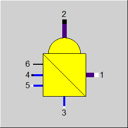
Line connections |
|
|
|
1 |
Primary side inlet (cold flow, inside tubes/drum) |
|
|
2 |
Primary side outlet (cold flow, inside tubes/drum) |
|
|
3 |
Secondary side inlet (hot flow, outside tubes) |
|
|
4 |
Secondary side outlet (hot flow, outside tubes) |
|
|
5 |
Supplementary condensate inlet (if available) |
|
|
6 |
(K*A)-controlling inlet |
|
General User Input Values Characteristic Lines Physics Used Displays Example
This component works analogously to the universal heat exchanger (component 55), but can be used for the vaporization of binary mixtures. In the vaporization of such a mixture, different concentrations of the cooling agent occur in the liquid phase and in the gaseous phase. In the component, these are shown as the result values XIL2 (mass fraction cooling agent in the liquid phase) and XIV2 (mass fraction cooling agent in the gaseous phase).
More line types are supported on the hot side. In particular, a binary fluid can now be present on this side as well, and also a universal fluid. The component is still not suitable for modeling a phase change on the hot side. A library change in the case of the universal fluid is not supported either.
Pressure drop limitations in off-design (Extras --> Model Options--> Calculation -->Relative pressure-drop maximum) :
As the pressure drop rises quadratically with the mass flow, pressure drops that are significantly too high can quickly arise in the event of a transgression of the nominal mass flow. These will then cause phase transitions and convergence problems. For this reason, pressure drop limitations have been installed.
Pinch point violations in the case of heat exchangers
Up to release 10.0, a pinchpoint violation was only determined subsequently in partial load, i.e. KA was calculated for the respective load case and from this the transferred heat quantity and then it was checked whether this heat quantity can be transferred at all at the correct temperature level. Since in the case of evaporation or condensation the temperature remains constant despite heat input or heat removal, there are cases where heat transfer is not physically possible despite the overall balance being correct. In this case, an error message was issued in Ebsilon.
The calculation has now been changed in such a way that the transferred heat quantity is reduced as far as it is still physically possible, with the minimum pinch point
can be set in a default value PINPMIN. This results in a correspondingly reduced heat transfer capabilityKA.
The user is informed of this by a warning message ("KA reduced to avoid pinchpoint violation") and can then adjust the part-load characteristic curve or the part-load exponent for KA accordingly so that the warning no longer occurs. The advantage, however, is that one gets a physically possible result in any case.
Furthermore, at the end of the calculation there is a check if there is a pinch point violation due to curved course of Q(T) (caused by significant changes of cp depending on the temperature). This can be verified by dividing the heat exchanger into individual sections.
This case can occur, for example, when on the hot side the cp at the inlet is significantly smaller than at the outlet (for example, steam that has a cp of about 2 kJ/kgK at high superheat, but more than 5 just above the boiling line). This means that this steam provides more heat at a lower temperature level than at a high one. At appropriately low degrees, this can be a limitation on the amount of heat transfer that is possible.
The QT diagrams take into account the non-linearity (curvature of the curves) in areas without phase change.
The flag FSPEC (deprecated) has been divided into two flags:
Note:
When loading a model that was created with Release 11 (or older), the corresponding values for FTYPHX, FSPECD, are determined from the value of the flag FSPEC, and FSPEC is set to “void” (-999). The model then calculates with these as before. If required, however, the flag FSPEC can still be used as well.
To remove ambiguity, the terms “primary side” and “secondary side” respectively have been replaced by “cold side” and “warm side” in the input screens. The cold side is the flow from Pin 1 to Pin 2 that is heated. The warm side is the flow from Pin 3 to Pin 4 that gives off the heat.
Design in the Case of Concurrent Flow (see: Heat Exchanger General Notes )
In the heat exchanger (Components 98) it is possible to carry out a design via the upper and lower terminal temperature difference also in the case of concurrent flow (FFLOW=1).
If both inlet temperatures are specified, the upper terminal temperature difference can only be determined iteratively. Usually this is no problem. If convergence problems occur in more
complex models, another design mode will have to be used.
Performance factor RPFHX
The quotient from the current value for k*A (result value KA) and the k*A expected in the respective load point due to the component physics and characteristic lines respectively (result value KACL) serves to assess the condition of a heat exchanger.
The quotient KA / KACL is displayed as result value RPFHX.
|
FTYPHX |
Type of heat exchanger Like in Parent Profile (Sub Profile option only) Expression = 0: General heat exchanger = 2: Evaporator |
|
FSPECD |
Calculation method in design-case Like in Parent Profile (Sub Profile option only) Expression = 1: Specification of the lower terminal temperature difference (=T4-T1) in the specification value DTN |
|
DTN |
Terminal temperature difference (nominal) for FSPEC = 1 or 11: lower terminal temperature difference T4 -T1 for FSPEC = 2 or 12: upper terminal temperature difference T3 - T2 for other values of FSPEC, DTN is not relevant |
|
DP12N |
Primary stream pressure loss (nominal) |
|
DP34N |
Secondary stream pressure loss (nominal) |
|
TOL |
Accuracy in the energy balance |
|
PINPMIN |
Minimum value for the pinch point (KA is reduced automatically if the pinch point would fall below this value) |
|
AL12CN |
Primary convection transfer coefficient (nominal) |
|
AL34CN |
Secondary convection transfer coefficient (nominal) |
|
FMODE |
Flag for the calculation mode design/off-design Expression =0: Global =1: local off-design (i.e. always off-design mode, even when a design calculation has been done globally) =2: special local off-design (Special case for compatibility with the earlier Ebsilon-versions, should not be used in new models, because the results of the real off-design calculations are not always consistent) =3: in design mode - use K*A regulating; in off-design mode - alpha characteristic line =4: all modes - use KA regulating |
|
FFLOW |
Flag for the direction of flow (see: Heat Exchanger General Notes ) Expression =0: counter current =1: concurrent |
|
FVOL |
Part-load pressure drop Expression =0: only depending on mass flow =1: depending on mass and volume flow =2: Constant (equal nominal value) |
|
FADAPT |
Flag for using the adaptation polynomial ADAPT/ adaptation function EADAPT Expression =0: Not used and not evaluated =1: Correction for k*A [KA = KAN * char line factor(K/KN) * polynomial] =2: Calculation of k*A [KA = KAN * polynomial] =1000: Not used, but ADAPT evaluated as RADAPT (Reduction of the computing time) = -1: Correction for k*A [KA = KAN * char line factor(K/KN) * adaptation function] = -2: Calculation of k*A [KA = KAN * adaptation function] = -1000: Not used, but EADAPT evaluated as RADAPT (Reduction of the computing time) |
|
EADAPT |
Adaptation function |
|
FFU |
Flag on/off Expression =0: Heat exchanger off =1: Heat exchanger on (active) |
|
FSPEC (deprecated) |
Combi switch for operation type and temperature definitions in the design mode (except for the last two modes FSPEC=3 and 23, which can be used for the off-design case as well. Expression = -999: unused (FSPECD and FIDENT used instead) old values: =1: General heat exchanger, given lower terminal temperature difference =2: General heat exchanger, given upper terminal temperature difference =3: General heat exchanger, given T4 =21: Evaporator, given lower terminal temperature difference =22: Evaporate, given upper terminal temperature difference =23: Evaporate, given T4 |
|
KAN |
Heat transfer coefficient *area (nominal) - Design Heat Transfer Capability |
|
M1N |
Mass flow cold side (nominal) |
|
M3N |
Mass flow hot side (nominal) |
|
V1N |
Specific volume at primary inlet, cold side (nominal) |
|
V3N |
Specific volume at secondary inlet, hot side (nominal) |
The parameters marked in blue are reference quantities for the off-design mode. The actual off-design values refer to these quantities in the equations used.
Generally, all inputs that are visible are required. But, often default values are provided.
For more information on colour of the input fields and their descriptions see Edit Component\Specification values
For more information on design vs. off-design and nominal values see General\Accept Nominal values
1st Characteristic Line CKAM1 FK1 = f (M1/M1N)
2nd Characteristic Line CKAM3 FK2 = f (M3/M3N)
(K*A)/(K*A)N = FK1 * FK2
|
Characteristic Line CKAM1: (k*A)-Characteristic Line: (k*A)1/(k*A)N = f (M1/M1N) |
|
X-axis 1 M1/M1N 1st Point |
|
Characteristic Line CKAM3: (k*A)-Characteristic Line: (k*A)2/(k*A)N = f (M3/M3N) |
|
X-axis 1 M3/M3N 1st Point |
Design Case (Simulation flag: GLOBAL=Design and FMODE=Design) |
||
|
|
If the lower terminal temperature difference is defined by FSPEC, then {
P4 = P3 - DP34N T4 = T1 + DTN H4 = f(P4,T4) M4 = M3 Q4 = M4 * H4 DQ = (Q3 - Q4)*(1-DQLR)
P2 = P1 - DP12N Q2 = Q1 + DQ M2 = M1 H2 = Q2/M2 T2 = f(P2,H2)
DTL = T4 - T1 (for FFLOW=Countercurrent) DTU = T3 - T2 (FFLOW=Countercurrent) LMTD = (DTU - DTL)/(ln(DTU) - ln(DTL)) (k*A) = DQ/LMTD (k*A)*LMTD = M2*H2 - M1*H1 (k*A)*LMTD = (M3*H3 - M4*H4)*(1.-DQLR) (4) }
if the upper terminal temperature difference is defined by FSPEC, then {
P2 = P1 - DP12N T2 = T3 DTN M2 = M1 H2 = f(P2,T2) Q2 = M2 * H2 DQ = Q2 - Q1
P4 = P3 - DP34N Q4 = Q3 - DQ/(1-DQLR) M4 = M3 H4 = Q4/M4 T4 = f(H4,P4)
DTLO = T4 - T1 (for FFLOW=countercurrent) DTUP = T3 - T2 (for FFLOW=countercurrent)
LMTD = (DTUP - DTLO)/(ln(DTUP) - ln(DTLO)) KAN = DQ/LMTD KAN*LMTD = M2*H2 - M1*H1 KAN*LMTD = (M3*H3 - M4*H4)*(1 - DQLR) } |
|
Off-design case (Simulation flag: GLOBAL=Part-load or FMODE=Part-load) |
||
|
|
F1 = (M1/M1N) ** 2 (at GLOBAL=Design: F1=1.0)
P2 = P1 - DP12N * F1 M2 = M1
Fk1 = f(M1/M1N) as per Characteristic Line 1, when GLOBAL=Design Fk1=1 Fk2 = f(M3/M3N) as per Characteristic Line 2, when GLOBAL=Design Fk2=1.0 KA = KAN * Fk1 * Fk2
F3 = (M3/M3N) ** 2 (when GLOBAL=Design: F3=1.0)
P4 = P3 - DP34N * F3 M4 = M3 + M5
Maximum/minimum values for the iteration { H2max = f(P2,T3) Q12max = M1 * (H2max - H1) H4min = f(P4,T1) Q34max = Q3 - M4 * H4min }
For FFLOW=Countercurrent{ Qmax = min(Q12max,Q34max) }
For FFLOW=Concurrent{ Initial estimate at the start of Iteration 1 QA = min(Q12max,Q34max) QM = QA*QA/(Q12max+Q34max)
Iteration1{ H2 = H1 + QM*(1-DQLR)/ M2 T2 = f(P2,H2) T4 = T2 H4 = f(P4,T4) QK = Q3 -M4 * H4 DQQ_1 = DQQ DQQ = QM - QK regula - falsi Method { Slope= (QM - QM_1)/(DQQ - DQQ_1) for Iteration step 1: Slope of the last global step QMU = QM - DQQ * Slope QM_1 = QM QM = QMU } DQ = | DQQ/((QM+QK)*.5) |
if DQ < TOL then iteration 1 ends else continue the iteration } Qmax = QM } Q12 = 0.5*Qmax Iteration2{ H4 = (Q3 - Q12/(1-DQLR) )/M4 T4 = f(P4,H4) H2 = H1 + Q12/M2 T2 = f(P2,H2) DTLO = T4 - T1 (for FFLOW=Countercurrent) DTUP = T3 - T2 (for FFLOW=Countercurrent) DTLO = T4 -T2 (for FFLOW=Concurrent) DTUP = T3 -T1 (for FFLOW=Concurrent) LMTD = (DTUP - DTLO)/(ln(DTUP) - ln(DTLO)) QQ = KA * LMTD DQQ_1 = DQQ DQQ = Q12 - QQ regula - falsi Method { Slope= (Q12 - Q12_1)/(DQQ - DQQ_1) for Iterations step 1: slope of the last step Q12X = Q12 - DQQ * Slope Q12_1 = Q12 Q12 = Q12X }
DQ = |DQQ /((Q12+QQ)*.5)| if DQ < TOL then iteration 2 ends else continue the iteration } KA*LMTD = M2*H2 - M1*H1 KA*LMTD = (M3*H3 - M4*H4) * (1 DQLR) |
|
 |
Display Option 1 |
 |
Display Option 2 |
Click here >> Component 98 Demo << to load an example.