EBSILON®Professional Online Documentation


|
Line connections |
|
|
|
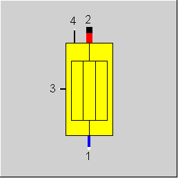
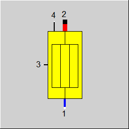
1 |
Primary inlet (cold side) |
|
|
2 |
Primary outlet (cold side) |
|
|
3 |
Heat flow from flue gas Connection to the attached flue gas zone, component 88 |
|
|
4 |
Information flow from bundle Connection to the attached main heating surface, component 89 |
|
General User Input Values Characteristic Lines Physics Used Displays Example
Together with components 89 (steam generator, main heating surface) and 88 (steam generator, flue gas zone), component 91 allows the representation of membrane pipe walls or supporting tubes in the area of a bundle heating surface that are usually integrated into the water/steam model in another place than the bundle. Apart from water/steam, however, thermal oil, two-phase fluid, and universal fluid are supported as primary fluid as well.
Module 91 only represents the primary side of an auxiliary heating surface. Therefore, use of this component, without component 88 representing the flue gas side (at PIN 3, connected to PIN 4 or 5 of flue gas zone 88) or without a corresponding main heating surface 89 (at PIN 4, connected to PIN 6 or 7 of main heating surface 89) will lead to errors.
Pressure drop limitations in off-design (Extras --> Model Options--> Calculation -->Relative pressure-drop maximum) :
As the pressure drop rises quadratically with the mass flow, pressure drops that are significantly too high can quickly arise in the event of a transgression of the nominal mass flow. These will then cause phase transitions and convergence problems. For this reason, pressure drop limitations have been installed.
Pinch point violation :
In case of a pinch point violation KA is nowOne can now position it and change its name and description. This description also appears as text on the macro display. reduced automatically (like for other heat exchangers) to avoid the pinch point violation. A warning is issued in this case.
Like other heat exchanges, the calculation model is based on the fundamental equations for the mass flow, pressure and enthalpy
- (1) M1 = M2
- (2) P1 = P2 + DP12
- (3) (k*A)*LMTD = M2*H2 - M1*H1
with the indices
- 1 for the primary inlet
- 2 for the primary outlet
For calculating the mean logarithmic temperature difference LMTD, the flue gas inlet and outlet temperatures of the components 88 or 90, connected via the logic line 3, are used. for this reason, component 89 is fully functional, only when line 3 is connected to component 88 (PIN 4 or 5).
It is assumed for mass flow and pressure, that M1 / M2 or P1 / P2 respectively are given at the connected lines. In each case, the missing value is calculated.
It is assumed that the heat transfer coefficient of an auxiliary heating surface is determined by the flow conditions and geometry of the main heating surface. Thus, the heat transfer coefficient is taken from the attached component 89, whereby the k-value of the main heating surface is modified with a correction factor CORR
- (4) kauxiliary= CORR * kmain
The calculation rules to evaluate the heat transfer coefficient are described in detail in component 89.
The identification of component 91 is defined as the calculation of CORR from (3) and (4), whereby one temperature on the flue gas side as well as in- and outlet temperature on the water/steam side must be known.
Taking over CORR for the Auxiliary Heating Surface
Like in many other components, when using the identification mode in the design case the result value is automatically transferred to the specification value too.
For this component it is the result value RED that is transferred to the specification value CORR.
A common identification of an auxiliary heating surface, component 91 in a group with other heating surfaces, as in the case of main heating surface, component 89, is currently not implemented.
|
FFLOW |
Flag for the type of heat exchanger (see HeatExchanger,General Notes ). Expression =0: counter current flow =1: Concurrent flow |
|
FMODE |
Flag for calculation mode Design/Off-design Expression =0: set as global |
|
DP12N |
Pressure loss 12 in the design case, in the design case, the given value is used exactly, in the off-design mode a correction is done with mass flow ratio and volume correction |
|
FIDENT |
Flag for component identification Expression =0: No identification |
|
CORR |
Correction factor for adjusting the heat transfer coefficient, which is taken from the main heating surface. |
|
A |
Heat transfer area of the auxiliary heating surface, usually the supporting pipes or the membrane wall. |
|
M1N |
Mass flow at the inlet (PIN 1) in the design case |
|
V1N |
Specific volume at the inlet (PIN 1) in the design case |
The identification value marked in blue is the reference value for the off-design mode. The actual off-design values refer to the values used in the equations.
Generally, all inputs that are visible are required. But, often default values are provided.
For more information on colour of the input fields and their descriptions see Edit Component\Specification values
For more information on design vs. off-design and nominal values see General\Accept Nominal values
It can be seen from the following table, whether CORR or T2 is to be specified:
|
|
Design |
Off-design |
||
|
|
FIDENT = no identification |
FIDENT = T2 specification |
FIDENT = no identification |
FIDENT = T2 specification |
|
CORR |
specified by user |
ignored |
specified by user |
ignored |
|
T2 |
calculated |
specified by user |
calculated |
specified by user |
No characteristic lines are used.
|
Design (Simulation flag: GLOBAL = Design and FMODE = Design) |
||
|
|
P2 = P1-DP12N |
|
|
Off-design (Simulation flag: GLOBAL = Off-design or FMODE = Off-design) |
||
|
|
DP12 = DP12N * V1/V1N * (M1/M1N)**2 P2 = P1 - DP12 |
|
|
All cases
|
||
|
|
M1 = M2 SPFMAK = k*A*CORR IF(no identification) Calculation of H2 from SPFMAK*LMTD = M2*H2 - M1*H1 ELSE Calculation of SPFMAK_ist from SPFMAK*LMTD = M2*H2 - M1*H1 Calculation of CORR fromSPFMAK and SPFMAK = CORR * (k*A)Main -M1*H1+M2*H2-M3*H3 = 0 H3 = SPFMAK*LMTD |
|
 |
Display Option 1 |
Click here >>Component_91 Demo<< to load an example.