EBSILON®Professional Online Documentation


|
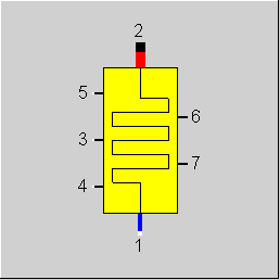
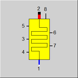
Line connections |
|
|
|
1 |
Cold side, inlet |
|
|
2 |
Cold side, outlet |
|
|
3 |
Heat flow from flue gas Connection to the attached flue gas zone, component 88 or component 90 |
|
|
4 |
Radiation exchange with component upstream in flue gas path |
|
|
5 |
Radiation exchange with component downstream in flue gas path |
|
|
6 |
Connection to auxiliary heating surface 1 |
|
|
7 |
Connection to auxiliary heating surface 2 |
|
General User Input Values Characteristic Lines Physics Used Displays Example
Component 89, together with components 88 (steam generator, flue gas zone) or 90 (steam generator, reaction zone) allows the modeling of the heat transfer in a heating surface of a steam generator.
It can be used as economizer, evaporator or super heater. It is used to model membrane walls in radiation areas or combustion chambers. I can also be used to model tube bundles. Water cooled walls or supporting tubes in the area of tube bundles can be represented using component 91 (steam generator, auxiliary heating surface).
Component 89 maps only the cold side (water / steam) side of the heating surface. Usage without components 88 or 90 to model the secondary (flue gas) side will therefore result in errors. Besides water/steam, also thermal oil, two-phase fluid, and universal fluid are supported as primary fluid.
Extensions for the Pressure Drop Calculation of the Flue Gas Side (for Components 88 and 89)
In Component 89, the pressure drop calculation of the flue gas side can be specified as Kernel expression, EDPO. As geometrical details of the heating surface are specified in Component 89, it is possible to access the corresponding specification values (like e.g. pipe diameter, partition, details on fins, etc.) and to implement an own pressure drop calculation (e.g. according to manufacturer information) in the Kernel expression EDPO.
The pressure drop on the flue gas side is calculated in Component 89 and transferred to Component 88. In Component 88 there is a flag for this, FDP, which switches between the previous pressure drop calculation according to Bernoulli’s principle and EDPO of Component 89.
Extensions for the Calculation of the Heat Transfer Coefficients of the Heating Surfaces (for Component 89)
As an alternative to the previous implementation according to VDI formalisms, the calculation of the individual heat transfer coefficients of the heating surface (alpha numbers) can be implemented by means of a corresponding Kernel expression (e.g. according to manufacturer information) in Component 89.
The following pair of specification values exists for this purpose in Component 89:
For the bundle heating surface the mean fluid flow velocity in the pipe is output as result value VELM.
Like other heat exchangers, the calculation model is based on the fundamental equations for the mass flow, pressure and enthalpy
- (1) M1 = M2
- (2) P1 = P2 + DP12
- (3) (k*A)*LMTD+QR_4+QR_5 = M2*H2 - M1*H1
with the indices
- 1 for the primary inlet (cold side)
- 2 for the primary outlet (cold side)
- 4 radiation flow from predecessor (with respect to flue gas arrangement)
- 5 radiation flow from successor (with respect to flue gas arrangement)
For calculating the mean logarithmic temperature difference LMTD, the flue gas inlet and outlet temperatures of that component 88 or 90 are used, which is connected using logic line 3. Therefore component 89 will work properly only when (PIN 3) is connected to (PIN 3) of component 88 or 90.
In case of mass flow and pressure, the component assumes that M1 / M2 or P1 / P2 respectively are defined on the connected lines. In each case, the missing value is calculated.
Pressure drop limitations in off-design (Extras --> Model Options--> Calculation -->Relative pressure-drop maximum) :
As the pressure drop rises quadratically with the mass flow, pressure drops that are significantly too high can quickly arise in the event of a transgression of the nominal mass flow. These will then cause phase transitions and convergence problems. For this reason, pressure drop limitations have been installed.
Pinch point violation :
In case of a pinch point violation KA is reduced automatically (like for other heat exchangers) to avoid the pinch point violation. A warning is issued in this case.
The heat transfer coefficient k*A is calculated from geometric data of the heating surface as well as process data (mass flows, temperatures, pressures, flue gas composition) following published calculations rules. In this aspect, component 89 differs from the other heat exchanger components, where k*A is calculated in design mode from given enthalpies or terminal temperature differences (see HeatExchanger,General Notes ). Depending on the parameter FIDENT, the behaviour of component 89 is as follows:
For the identification mode there are new variations FIDENT=“T2 given validable“, both for calculating the fouling and for calculating the rating number. Previously, for the validation a temperature specified from outside was treated as a constant quantity. In the new modes, an equation is generated into which this temperature is integrated, so that a statistical reconciliation can take place.
Thus, the calculation mode DESIGN or OFF-DESIGN has no influence on the behaviour of component 89 concerning the heat transfer calculation.
The k-value results from the inner heat transfer ALI, the outer heat transfer by radiation ALR and by convection ALC as well as from heat conductivity LAMDBA, efficiency factor EFF and fouling factor KFOUL:
AA, AI, AM are the specific surface areas of the heat-exchanger tubes with respect to outer, inner and average surface. S is the wall thickness.
LAMBDA is stored taking into account the dependency on material and temperature. The heat transfer coefficients are calculated from the VDI Heat Atlas (7th edition, 1994), where a differentiation is made between the tube bundles, radiation areas and combustion areas:
The calculation rule for the inner heat transfer can be chosen by the switch FPHASE. Alternatively, there is the option to switch automatically according to the enthalpies at inlet and outlet.
If FPHASE = AUTOMATIC, then bubble boiling is assumed, if (H1+H2)/2 is in the wet steam area.
The convective heat transfer is set to 0 for radiation zones.
Radiation fractions of coke, ash, soot according to VDI-Ke. Particle radiation is taken into account only in the combustion zone.
Besides the heat transfer by radiation within a flue gas zone, component 89 can also take into account the radiation exchange between a heating surface and the flue gas volume of components upstream or downstream, in the direction of flue gas flow. For this purpose, PIN 5 must be attached to PIN 7 of the components 88 or 90, which represents the flue gas part of the successor and, if necessary, PIN 4 with PIN 6 of the predecessor. The calculation of the radiation exchange is based on the following assumptions:
Identification of the component means calculating EFF or KFOUL using e.g. equations (3) and (5), if one of the flue gas temperatures and both water / steam in- and outlet temperature are given. Currently, the component allows only for calculating the efficiency factor EFF with a given fixed fouling KFOUL. The calculated efficiency is displayed as the result REFF.
In a steam generator there are sometimes heating surfaces, which form a unit for the process (e.g. reheater 1 or evaporator), but which consist of several constructional groups, installed in separate flue gas zones. Most of the time there is no temperature / enthalpy information available from measurements among the constructional groups. Thus, an identification of each group using e.g. equations (3) and (5) is not possible. However, a common efficiency factor for the unit as a whole can be calculated from the temperatures at inlet and outlet.
For this purpose, a group index (IGROUP) for the identification can be assigned in component 89. All heating surfaces, which should have a common efficiency factor, have the same group index, and up to 10 groups are allowed, 1<=IGROUP<=10. One of the heating surfaces within the group is then set in the identification mode (FIDENT = T2 given, efficiency factor calculated), all other ones in FIDENT = no identification. All heating surfaces within a group defined in this way will have the same efficiency factor as a result.
In case the model is to be used in the simulation mode without an identification of the groups, then for one heating surface in the identification mode, FIDENT should be set to "no identification" and for ALL heating surfaces of the group, IGROUP = 0 is to be set.
In the flue gas zone, there are frequently smaller heating surfaces along with the main heating surfaces in the form of construction parts (supporting tubes, cooled walls), through which water and steam flow. These auxiliary heating surfaces are often arranged in a different part of the water / steam circuit than the main surface, but share the same flue gas inlet and outlet conditions with the main heating surface. Component 91 is designed to represent these auxiliary heating surfaces.
The heat transfer in a flue gas zone is dominated by the geometry of the main heating surface. Thus, the heat transfer coefficient calculated in component 89 is transferred to component 91, in case it is connected. To support this, an optional auxiliary heating surface (with its PIN 4) can be attached to the main heating surface using the logic lines PIN 6 or 7 of component 89. A maximum of two auxiliary surfaces for each component 89 is allowed.
Using an auxiliary heating surface in a flue gas zone in addition to a main heating surface makes sense only if the main heating surface is configured as a bundle tube by setting FHEAT = bundle. If FHEAT = radiation / combustion zone, the main heating surface normally represents the membrane wall.
In the case of Component 89 the possible heat exchange is explicitly calculated at a specified geometry. REFF represents here the ratio between the real (fouled) and ideal (clean) heat exchanger. Thus here REFF is a measure for the condition (performance factor) of the heat exchanger.
The pressure drop is displayed as result value DP, independently of whether it was calculated in the component or inlet and outlet pressure were given from the outside.
Note:
The formulae used in the component are only suitable for Reynolds numbers <10^6. The Reynolds number is limited to 2 * 10 ^ 6 and a warning will be output.
Further results are:
are now output as result values,
For a better comprehension of the heat transfer by radiation on the flue gas side, the following result values are calculated and displayed besides
the following result values are calculated and displayed besides
The minimum value for the terminal temperature difference has been reduced from 3 to 1 K.
The part-load behaviour of component 89 results from the implemented model equations. For an adaptation to the real plant behaviour, characteristic lines and adaptation polynomials are provided. The switches FCHR and FADAPT allow you to choose between a characteristic line and an adoption polynomial.
For the emissivity and the absorption ratio it is possible for the user to implement their own calculation algorithms by means of kernel expressions. The previous implementation is stored as default.
The list of available types of tube and fin material has been expanded by 58 new types of material derived from a research paper published by Mannesmann.
To make it easier to determine the characteristic line, result values M1M1N and EFFEFFN have been added in this component; they show the ratio of the prevailing mass flow and the prevailing effectivity respectively to the corresponding nominal value.
|
FFLOW |
Flag for the heat-exchanger type (see HeatExchanger,General Notes ). Expression =0: Counter Current flow =1: Concurrent flow |
|
FMODE |
Flag for calculation mode Design/Off-design Expression =0: set as global |
|
FDP |
Flag for the calculation of the pressure loss Expression =0: calculated in the component from DP12N |
|
DP12N |
Pressure loss between ports 1 and 2 in design mode. If design mode is set, the prescribed value is used. If off-design is set, pressure will be corrected with mass flow and specific volume. |
|
FIDENT |
Flag for component identification Expression =0: no identification or identification in a group with another component 89 with a common efficiency factor. In case of a group identification, the related components shall have the same IGROUP number. In the case of no identification, IGROUP shall be 0 =1: T2 given (constant), efficiency is calculated. In case identification of several components 89 is to be done with a common efficiency factor, exactly one component within the group shall have FIDENT = 1, the others shall have FIDENT=0. =2: T2 given (constant), fouling is calculated. This option is currently not implemented. =3: T2 given (validable), efficiency is calculated. =4: T2 given (validable), fouling is calculated. This option is currently not implemented. =5: T2 and efficiency factor given, heating surface area calculated (The calculated surface is output in the result value RA.) |
|
IGROUP |
Group Index: Component 89 allows for a group identification of several components with a common efficiency factor. The membership of a component 89 in such a group is marked by a common group index, 0<=IGROUP<=10. IGROUP = 0 does not mark any group, but must be set, if no identification is to be done. A maximum of 10 identification groups are possible. |
|
DIAM |
Inner diameter of the heat exchanger tubes |
|
THWALL |
Wall thickness of the heat exchanger tubes |
|
PITCHL |
Longitudinal pitch of the tube bundle (distance of successive tubes in the flow direction of the flue gas. PITCHL will be evaluated only if FHEAT = tube bundle. It is not relevant if FHEAT = radiation or combustion zone, because component 89 represents a membrane wall in these cases) |
|
PITCHT |
Transversal pitch of the tube bundle (distance of successive tubes perpendicular to the flow direction of the flue gas. PITCHT will be evaluated only if FHEAT = tube bundle. It is not relevant if FHEAT = radiation or combustion zone, because component 89 represents a membrane wall in these cases) |
|
FTUBE |
Tube arrangement Expression =0: inline =1: staggered FTUBE will be evaluated only if FHEAT = tube bundle. It is not relevant if FHEAT = radiation or combustion zone, because component 89 represents a membrane wall in these cases |
|
KFOULN |
Additional thermal resistance to be taken into account on calculating the heat transfer coefficient. Nominal value that can be adjusted using characteristic lines and/or adaption polynomial depending on the specification values FADAPT and FCHR |
|
FHEAT |
Code for heating surface type: Expression =0: tube bundle, represents tube coils that are arranged perpendicular to the direction of flue gas flow =1: radiation zone, represents cooled water walls (membrane wall); radiation zones do not house tube bundles across the direction of flow of the flue gas. Thus, specification values referring to the geometry of tube bundles are meaningless; convective heat transfer is ignored. =2: combustion zone, similar to the radiation zone; the radiation zone takes into account radiation emission of gas, ash and soot, the combustion zone in addition the emission of fuel particles (coke) |
|
FMATT |
Code for tube material : Material Properties of Steel =-1 : Lambda calculated by Kernel expression EMATT |
|
EMATT |
Function for heat conductivity for tube material function evalexpr:REAL; |
|
FPHASE |
Code for calculating the inner heat transfer type Expression =0: Automatic; depending on the average enthalpy 0.5*(H1+H2), one of the other options is selected =1: Single phase, water; calculation according to Gnielinski under the assumption of a single phase flow in the heating surface. In case the average enthalpy is in the wet steam area, the heat transfer is calculated with water. =2: Single phase steam; calculation according to Gnielinski supposing single phase flow in the heating surface. In case the average enthalpy is in the wet steam area, the heat transfer is calculated with water. =3: Nucleate boiling; Calculation of a heat transfer coefficient that depends only on the heat flux density by assuming bubble boiling within the complete heating surface. |
|
A |
Heat exchange area of the tube bundle or the membrane wall |
|
FFIN |
Code for fin type ( Relevant only if FHEAT = 0):
Expression =0: Plain pipe =1: Circular fins =2: Rectangular fins =3: Continuous fins |
|
CFIN |
C- value for the calculating the outer heat transfer coefficient of finned tubes according to Schmidt: NU =CFIN * RE^0.625 *PR^0.333.Typical value is CFIN=0.28 for in-line, CFIN=0.3333 for staggered arrangement. |
|
HFIN |
Fin height, relevant only if FFIN = CIRCULAR FIN |
|
LFIN |
Fin length - for rectangular fins LFIN>=WFIN;
(see VDI Wärmeatlas, Kapitel M1) |
| WFIN |
Fin width (Rectangular fins) - for Rectangular fins WFIN = Specification value - Connected fins (Length and width are determined by the arrangement of the pipes) :
(see VDI Heat Atlas, Chapter M1)
|
|
PFIN |
Fin pitch (number of fin / tube length)(distance between neighbouring fins), relevant only if FFIN = CIRCULAR FIN |
|
THFIN |
Fin thickness, relevant only if FFIN = CIRCULAR FIN |
|
FMATF |
Code for fin material : Material Properties of Steel =-1 : Lambda calculated by Kernel expression EMATF Relevant only when FFIN=1. |
|
EMATF |
Function for heat conductivity for fin material |
|
PHIINC |
Angle between the flow direction of the flue gas and the tube coils; valid only if FHEAT = 0; the standard value 90° corresponds to perpendicular flow. |
|
NTUBES |
Number of tubes, through which flow is parallel on the water / steam-side; does not necessarily always correspond to the number of tubes in one layer (seen from the flue gas side), but it is usually an integer multiple of the same (flow = 1/2, 1, 2, 3, 4, ...) |
|
EFFN |
Efficiency factor for correcting the inaccuracies in the model or the contamination states in accordance with: EFF/K = 1/ALO + 1/ALI*AA/AI + S/LAMBDA*AA/AM + KFOUL; depending upon the specification values FADAPT and FCHR, it can be corrected with characteristic curves and/or adaptation polynomials. |
|
CSASH |
Relative cross-section of the ash for absorptions, typical value 0.25
The parameters CSASH, DIAASH and DISTASH configure the fraction of ash radiation in the total emission of the flue gas. |
|
DIAASH |
Mean particle diameter of the ash, typical value 16*10**-6m
The parameters CSASH, DIAASH and DISTASH configure the fraction of ash radiation in the total emission of the flue gas. |
|
DISTASH |
Control parameter of the Rosin-Rammler distribution of the ash particles, typical value 1.5
The parameters CSASH, DIAASH and DISTASH configure the fraction of ash radiation in the total emission of the flue gas. |
|
SOOTCONT |
Soot content of the flue gas; used for calculating the fraction of soot emission in solid form in the total emission of the flue gas |
|
FADAPT |
code for using the adaptation polynomial ADAPT/ adaptation function EADAPT Expression =0: not used and not evaluated =1: EFF=EFFN*char. line* polynomial =2: EFF=EFFN*polynomial; if FCHR=0 is used at the same time, the characteristic line is ignored. =3: KFOUL=KFOULN*char. line*polynomial =4: KFOUL=KFOULN*polynomial; if FCHR=1 is used at the same time, the characteristic line is ignored. =5: KA= polynomial*KAN =1000: not used but ADAPT evaluated as RADAPT (Reduction of the computing time)
= -1: EFF=EFFN*char. line* adaptation function = -2: EFF=EFFN*adaptation function; if FCHR=0 is used at the same time, the characteristic line is ignored. = -3: KFOUL=KFOULN*char. line*adaptation function = -4: KFOUL=KFOULN*adaptation function; if FCHR=1 is used at the same time, the characteristic line is ignored. = -5: KA=adaptation function*KAN = -1000: not used but EADAPT evaluated as RADAPT (Reduction of the computing time) |
|
EADAPT |
Adaptation function (input) |
|
FCHR |
Code for using the characteristic lines Expression =0: EFF/EFFN=f(M1/M1N); characteristic line is ignored, if FADAPT=2 is set. =1: KFOUL/KFOULN=f(M1/M1N); characteristic line is ignored, if FADAPT=4 is set. |
|
FVALKA |
Validation of k*A (only in off-design) Expression =0: KAN is used without validation |
|
IPS |
Index of the pseudo-measurement point for the validation of k*A |
|
FEM |
Flag for Calculation of emissivity and absorption ration Like in Parent Profile (Sub profile option only) Expression =0: By internal formulas =1: By internal formulas with correction factors EEM and EABS =2: By Kernel expressions EEM and EABS |
|
EEM |
Function for emissivity |
|
EABS |
Function for absorption |
|
EMWALL |
Wall emissivity |
|
FALI |
Flag for switching the calculation of the internal heat transfer coefficient according to EALI on and off respectively Like in Parent Profile (Sub profile option only) Expression =0: By internal formulas =1: By Kernel expressions EALI |
|
EALI |
Kernel expression for the internal heat transfer coefficient (result value ALI) |
|
FALC |
Flag for switching the calculation of the external heat transfer coefficient by convection according to EALC on and off respectively Like in Parent Profile (Sub profile option only) Expression =0: By internal formulas =1: By Kernel expressions EALC |
|
EALC |
Kernel expression for the external heat transfer coefficient by convection (result value ALC). |
|
FALR |
Flag for switching the calculation of the external heat transfer coefficient by radiation according to EALR on and off respectively Like in Parent Profile (Sub profile option only) Expression =0: By internal formulas =1: By Kernel expressions EALR |
|
EALR |
Kernel expression for the external heat transfer coefficient by radiation (result value ALR) |
|
EDPO |
Function for external (flue gas) pressure drop (see under "General") |
|
M1N |
mass flow at inlet in the design case |
|
V1N |
Specific volume at the inlet in the design case |
|
KAN |
Heat transfer coefficient (nominal) |
The identification value marked in blue is the reference value for the off-design mode. The actual off-design values refer to the values used in the equations.
Generally, all inputs that are visible are required. But, often default values are provided.
For more information on colour of the input fields and their descriptions see Edit Component\Specification values
For more information on design vs. off-design and nominal values see General\Accept Nominal values
It can be seen in the following table, whether T2, efficiency factor or heating surface area is to be specified:
|
|
Design |
Off-design |
||||
|
|
FIDENT = no identification |
FIDENT = T2 specification, efficiency factor calculation |
FIDENT = T2 and efficiency factor specification, heating surface area calculation |
FIDENT = no identification |
FIDENT = T2 specification, efficiency factor calculation |
FIDENT = T2 and efficiency factor specification, heating surface area calculation |
|
efficiency factor |
EFFN to be specified by user, REFF=EFFN |
ignored, REFF calculated |
EFFN to be specified by user, REFF=EFFN |
EFFN and char. line or adaption polynomial to be specified by user, REFF = f(EFFN, char. line or polynomial) |
ignored, REFF calculated |
EFFN and char. line or adaption polynomial to be specified by user, REFF = f(EFFN, char. line or polynomial) |
|
T2 |
calculated |
to be specified by user |
to be specified by user |
calculated |
to be specified by user |
to be specified by user |
|
heating surface area |
to be specified by user |
to be specified by user |
calculated |
to be specified by user |
to be specified by user |
calculated |
The following medium combinations are possible:
|
Primary |
Secondary |
|
Water or steam
|
in the connected component 88 or 90: Flue gas |
1st characteristic line FAC/FAC0 = f (M1/M1N)
(EFF/EFFN = f(M1/M1N) (FCHR=0) or KFOUL/KFOULN=f(M1/M1N) (FCHR=1)
|
Characteristic line 1: (k*A)-characteristic line: (k*A)1/(k*A)N = f (M1/M1N) |
|
X-axis 1 M1/M1N 1st point |
|
Design (Simulation flag: GLOBAL = Design and FMODE = Design) |
||
|
|
P2 = P1-DP12N |
|
|
Off-design (Simulation flag: GLOBAL = Off-design or FMODE = off-design) |
||
|
|
DP12 = DP12N * V1/V1N * (M1/M1N)**2 P2 = P1 - DP12 |
|
|
All cases
|
||
|
|
M1 = M2
-M1*H1+M1*H2-M3*H3-M4*H4-M5*H5= 0
Calculation of average pipe values t_rg = (T3+T4)/2.0 p_rg = (P3+P4)/2.0 h_med = (H1+H2)/2.0 p_med = (P1+P2)/2.0 t_med = (T1+T2)/2.0
Estimation of wall temperature t_wall = t_rg - 0.9*(t_rg-t_med)
Calculation of layer thickness according to VDI-Kc
Calculation of form factors for predecessor and successor according to VDI-Kb Fixed point iteration 1: (efficiency factor) Fix point iteration 2: (Wall temperature with average pipe values) calculate emissivity according to VDI- Kc (gas radiation) or according to VDI-Ke (combustion zones) heat transfer through convection according to VDI-Gf (plain tube) or VDI-Mb (finned tube) heat transfer through radiation ALR = BOLTZMANN*EMMIWAND/(1-(1-EMMIWAND)*(1-absorptionsvh)) *(emissivitaet*t_rg+TABS)**4-absorptionsvh*(t_wand+TABS)**4) /(t_rg-t_wall); inner heat transfer according to VDI-Gb (single phase) or VDI-Hbb (bubble boiling) k-value EFF/K = 1/ALO + 1/ALI*AA/AI + S/LAMBDA*AA/AM + KFOUL Wall temperature t_wall = t_rg - kvalue/(BEWERTUNG*alpha)*(t_rg-t_med) END Fix point iteration 2
IF (no identification) Calculation of H2 from (k*A)*LMTD +QR_4+QR_5= M2*H2 - M1*H1 ELSE Calculation of (k*A)_ist from (k*A)*LMTD +QR_4+QR_5 = M2*H2 - M1*H1 Calculation of EFF from k_ist and EFF/K = 1/ALO + 1/ALI*AA/AI + S/LAMBDA*AA/AM + KFOUL
END Fix point iteration 1
H3 = Q2-Q1-QR_4-QR_5
|
|
|
|
|
|
 |
Display Option 1 |
Click here >> Component_89 Demo << to load an example.