EBSILON®Professional Online Documentation


|
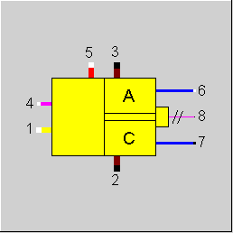
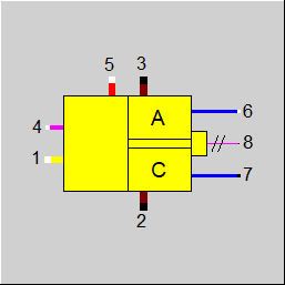
Line connections |
|
|
|
1 |
Oxidation gas inlet (e.g. air, O2) |
|
|
2 |
Off-gas (cathode) |
|
|
3 |
Off-gas (anode) |
|
|
4 |
Fuel gas inlet |
|
|
5 |
Steam inlet(only for old version with reformer) |
|
|
6 |
Cooling water inlet |
|
|
7 |
Cooling water outlet |
|
|
8 |
Generated electrical power |
|
General User Input Values Characteristic Lines Physics Used Displays Example
For this component, there has been a complete redesign in Ebsilon Professional Release 6.0. If, for compatibility reasons, it is required to reproduce the results of former calculations, it is possible to switch to the old calculation mode by setting FSPEC = "old mode".
While in the old mode, the reformer was integrated to component 82, the new mode requires a separate modeling of the reformer. For this purpose, you can use component 95 which calculates the chemical equilibrium (instead of a global description by characteristic lines). Therefore, a more detailed consideration is possible.
In the new calculation mode, there is a classification of different types of fuel cells. Use the parameter FSPEC to switch between these types. They are different by the used fuel gas and by the substances that appear at the anode and the cathode. The types implemented in EBSILON®Professional are PEM, PAFC, MCFC and SOFC.
For all types (in the new calculation mode), it is required to specify the mass flow, the temperature and the pressure of the inlet flows (fuel, oxidation gas and cooling water) and the chemical composition of fuel and oxidation gas. Steam, air or universal fluid may also be used as a cooling medium.
According to the specified fuel cell type, a chemical conversion is calculated. The conversion rates are determined by the specification parameters ECONH2 and ECONCO. The resulting reaction products are distributed to anode and cathode according to the picture above. Unused portions of the fuel gas are added to the anode outlet, unused portions of the oxidation gas are added to the cathode outlet.
The generated electrical powers and the temperature of anode and cathode off-gas are calculated using the specified efficiencies and losses:
For the first five of these quantities, a mass flow dependency can be specified by characteristic lines.
Specification of voltage, frequency and type of current in the component:
There is the option of specifying the voltage (VOLT), frequency (FREQ) and type of current (NPHAS) as the default value in the component.
The flags FVOLT and FFREQ are used to set whether the specification is to be made by the new specification values VOLT and FREQ respectively (0) or externally as a measured values on the electrical line (-1).
|
FMODE |
Calculation mode Expression =0: GLOBAL =1: Local off-design |
|
FSPEC |
Type of fuel cell: Like in Parent Profile (Sub Profile option only) Expression =0: Old mode (including reformer) =1: PEM =2: PAFC =3: MCFC =4: SOFC |
|
ETAEN |
Electrical efficiency = QEN/(NCV*M1N) |
|
ETACN |
Cooling efficiency = QCN/(NCV*M1N) |
|
ETAON |
Cathode off-gas efficiency = QON/(NCV*M1N) |
|
ETALN |
Degree of loss = QLOSS/(NCV*M1N) |
|
ETAANN |
Anode efficiency |
|
ECONH2 |
Conversion rate H2 |
|
ECONCO |
Conversion rate CO |
|
EDCAC |
Transformation efficiency DC to AC |
|
FFUEL |
Type of fuel (old mode only) Like in Parent Profile (Sub Profile option only) Expression =0: Hydrocarbon =1: Hydrogen |
|
ALAM |
Air ratio (air to air stoichiometric, old mode only) |
|
DP12N |
Pressure loss between line 1 and 2 (nominal) |
|
DP67N |
Pressure loss between line 6 and 7 (nominal) |
|
FVOLT |
Flag for the method for specification of voltage Like in Parent Profile (Sub Profile option only) Expression =0: Defined by specification value VOLT =-1: Voltage given externally on electrical outlet |
|
VOLT |
Voltage (on electric lines) |
|
FFREQ |
Flag for the method for specification of frequency Like in Parent Profile (Sub Profile option only) Expression =0: Use specification value FREQ =-1: Frequency given externally on electrical outlet |
|
FREQ |
Generator frequency |
|
NPHAS |
Type of current Like in Parent Profile (Sub Profile option only) Expression =0: Direct current =1: One-phase alternating |
|
M1N |
Air mass flow (nominal) |
|
M4N |
Fuel mass flow (nominal) |
|
M6N |
Cooling water mass flow (nominal) |
|
V1N |
Specific volume of the oxidizer (nominal) |
|
V6N |
Specific volume of the cooling water (nominal) |
The specification values marked in blue are reference values for the off-design calculations.
Generally, all inputs that are visible are required. But, often default values are provided.
For more information on colour of the input fields and their descriptions see Edit Component\Specification values
For more information on design vs. off-design and nominal values see General\Accept Nominal values
|
Characteristic line 1: ETAE-characteristic line: ETAE/ETAEN = f (M4/M4N) |
|
X-axis 1 M4/M4N 1st point |
|
Characteristic line 2: ETAC-characteristic line: ETAC/ETACN = f (M4/M4N) |
|
X-axis 1 M4/M4N 1st point |
|
Characteristic line 3: ETAO-characteristic line: ETAO/ETAON = f (M4/M4N) |
|
X-axis 1 M4/M4N 1st point |
|
Characteristic line 4: ETAL-characteristic line: ETAL/ETALN = f (M4/M4N) |
|
X-axis 1 M4/M4N 1st point |
|
Characteristic line 5: ETAAN-characteristic line: ETAA/ETAAN = f (M4/M4N) |
|
X-axis 1 M4/M4N 1st point |
|
Design case (Simulation flag: GLOBAL = Design case and FMODE = GLOBAL) |
||
|
|
CORE=1 CORC=1 CORO=1 CORL=1
F1 = 1 F6 = 1 |
|
|
Off-design (Simulation flag: GLOBAL = Off-design or FMODE = Local Off-design) |
||
|
|
CORE = f(M4/M4N) from characteristic line 1 CORC = f(M4/M4N) from characteristic line 2 CORO= f(M4/M4N) from characteristic line 3 CORL = f(M4/M4N) from characteristic line 4
F1 = (M1/M1N ** 2) * (V1/V1N) F6 = (M6/M6N ** 2) * (V6/V6N) |
|
All cases |
||
|
|
QZU = D4*(Hu4+H4)+D1*H1
DQE = ETAEN*CORE*QZU DQC = ETACN*CORC*QZU DQO = ETAON*CORO*QZU DQL = ETALN*CORL*QZU DQA = QZU-(DQE-DQC-DQO-DQL)
Composition and mass flow line 2: if FFUEL = Hydrocarbon then composition owing to hydrogen combustion and DQE+DQO mass flow owing to hydrogen combustion and DQE+DQO else composition owing to hydrogen combustion and DQE+DQO+DQC+DQL mass flow owing to hydrogen combustion and DQE+DQO+DQC+DQL endif
Composition line 3: From combustion calculation line 1/ line 4 minus composition line 2 plus composition line 5
M1M4R = Mass flow ratio line 1/ line 4 from combustion calculation M1 = M1M4R *M4
M3=M1+M4+M5-M2
DP12 = DP12N* F1 P2 = P1 DP12 P3 = P2
DP67 = DP67N* F6 P7 = P6 DP67
H8 = DQE H7 = H6+DQC H2 = DQO/M2 H3 = ((H5-2500.)*M5+DQA)/M3 |
|
 |
Display Option 1 |
Click here >> Component 82 Demo << to load a PAFC fuel cell example.
Click here >> Component 82 PEM << to load a PEM fuel cell example.
Click here >> Component 82 SOFC << to load a SOFC fuel cell example.
Click here >> Component 82 MCFC << to load a MCFC fuel cell example.