EBSILON®Professional Online Documentation


|
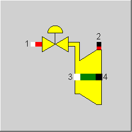
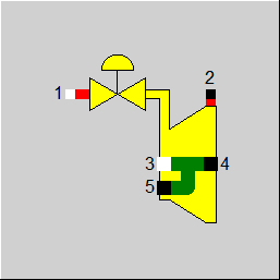
Line connections |
|
|
|
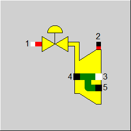
1 |
Inlet Steam |
|
|
2 |
Outlet Steam |
|
|
3 (5) |
Shaft inlet If shaft inlet 3 should be active, then that is |
|
|
4 |
Shaft exit |
|
|
5 |
Shaft outlet
Shaft / "None" If shaft outlet 5 should be active, then that is
|
|
General Shaft connection Calculation User Input Values Characteristic Lines Physics Used Results Displays Example
Component 58 models the control of the nozzle section. The limits of balance are at the inlet in front of the throttling elements and at the outlet behind the control valves.
Usually, the component is placed between the boiler or the super heater and further turbine stages. In comparison to a conventional turbine arrangement consisting of control valve and several turbine stages, the control by nozzle sections substitutes for the control valve and the first turbine stage.
The nozzle section control is modelled by a throttled and an unthrottled mass flow, each led through the steam turbine. Thereafter, both the mass flows are mixed and led to the next turbine stage. The split relation is taken from the second characteristic line.
In the past, the second shaft connection on component 58 (steam turbine) was a shaft input. This made it possible to connect several turbine discs in series for component 58, so that the shaft power was added together.
The reverse case of power splitting for component 58 could not be represented graphically in the past. However, there was a switch FQ (power flow) for the calculation, with which the calculation could be changed, but with the drawback that the graphical representation then did not match the calculation.
The reverse power flow can now also be displayed graphically. Shaft connection 5 should be used for this.
To enable a corresponding visualisation, the previously existing connection has been hidden and the new connection has been positioned in the same place. Usually, either the input or the output is used and the unused connection should then be hidden. In principle, however, the software also allows both connections to be used simultaneously.
As with the previous second shaft connection, the power must also be specified on the new connection. The turbine can only calculate the power at the main shaft output.
The new connection means that the FQ switch is now superfluous. However, it is still available for compatibility reasons, but has been labelled as ‘obsolete’.
In addition, a comment message may be displayed to indicate the possibility of using the new connection. The switch also reverses the calculation direction for the new shaft connection.
A new result value QSHAFT has been implemented for component 58 (also for component 6, 58), which outputs the shaft power generated in the component, regardless of which connections it is distributed to or which shaft power is added.
A nozzle section consists of a small number of nozzles (mostly between three and five), which in the partial-load mode are either
The following values are defined through thermodynamic conditions:
inlet enthalpy H1 by the preceding component (mostly boiler or super heater) and
outlet pressure P2 by the following component (mostly turbine stage or condenser).
In component 58
are determined just as in the components 6 (simple steam turbine) and 57 (gas turbine (extended)). The methods for determining these three values are described below.
Inlet pressure P1
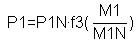
In case of full load or design, the inlet pressure P1 is determined by the nominal inlet pressure P1N.
P1 = P1N
In case of off-design or checking, P1 results either from characteristic line 3
or is determined according to the steam cone rule.
P1 calculation in partial load
At partial load, component 58 calculates the inlet pressure p1 as a function of the mass flow, outlet pressure and its specific volume from the Stodola Law:
See also: Part-load - Steam Turbine
In the chapter "Part load calculation of the steam turbine", M1N, P1N, P2N and V1N designate the nominal values in the design case or M1, P1, P2 and V1 the corresponding variables under the current conditions. As in the design case, the outlet pressure P2 is always determined by external components.
P1 given externally:
Analogous to the other steam turbine components (6, 56), a pressure specification from outside has been enabled also for this component.
Outlet enthalpy H2
In case of full load or design, the outlet enthalpy is determined by H1 and P1 as well as P2 with the isentropic nominal efficiency known as presupposition.
In case of off-design or checking, H2 results from two state changes:
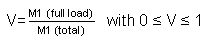
a "full load" state change for the completely opened nozzle elements from (P1, H1) to (P2, H2a) with nominal efficiency. Mass flow M, which is submitted to this change of condition, results from the mass flow cut V to
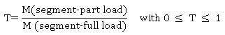
a "part-load" state change of the throttled nozzles consists of two sections:
The outlet condition H2 is determined by a mixture of the two conditions H2a and H2b
H2 = H2a*V + H2b*(1-V)
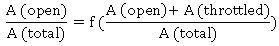
The two essential quantities for the using the model
are determined by means of characteristic line 2. In this characteristic line the following is plotted:
on the x-axis
on the y-axis

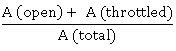
A(total) : total profile of all nozzles
A(open) : total profile of all opened nozzles
A(throttled) : profile of the throttled nozzles
ETAI (Results):
In this component, the result value ETAI is an averaged value over the individual sectors and does not contain the losses by the throttling. A new result value ETAIEFF has been implemented. It indicates the effective overall efficiency (from the inlet line upstream of the governing stage up to the outlet line). Also the result values VM1, VM2, and DH2L are such averaged quantities (therefore VM1 does not match with VM of Line 1).
The following example explains the setting of the characteristic line as well as its processing in the program.
Example:
A nozzle section contains three throttling elements that admit in each case 50%, 30% and 20% of the control wheel profile. The following switching mode is possible:
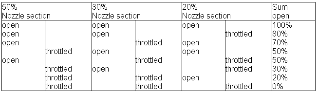
The following characteristic line must be available:
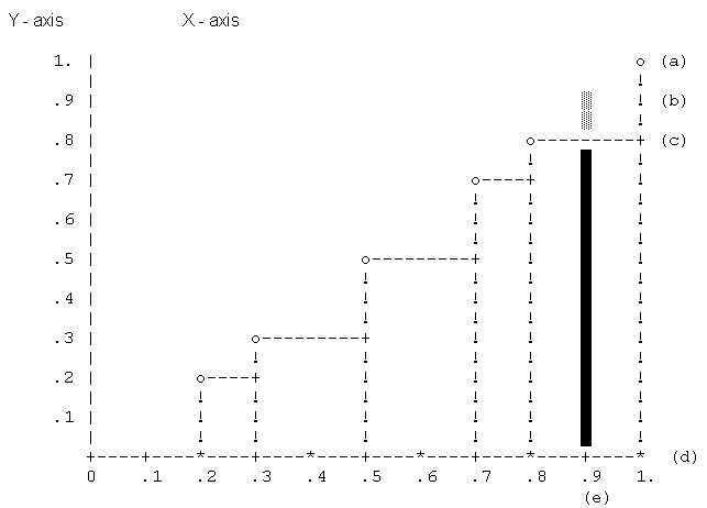
The diagram shows an example, in which the nozzle section is admitted with a mass flow running up to 90% of that mass flow that could pass through in case of completely opened nozzles (point e). Under same pressure and temperature conditions, this mass flow corresponds to 90% of full load mass flow.
The diagram shows that one of the nozzle sections covers 80% of the total profile (o-points at 0.8 and 1.0), thus the 90% case is realized as follows:
part throttling of this 20% nozzle section
complete opening of all other nozzle sections (remaining 80%)
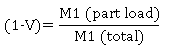
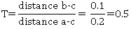
The reduced mass flow V (that is, the mass flow running through opened nozzles related to total mass flow) results from the diagram
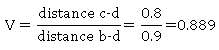
The part-load admission degree (that is, the mass flow running through the partly throttled nozzle related to the mass flow that could run through the nozzle without throttling) can also be read.
Shaft power
The shaft power results from the mass flow and the enthalpy difference under consideration of the mechanical losses and using the first fundamental principle.
Implementing a load-independent mechanical loss (QLOSSM) (see Release 12)
The sequence in which the proportional and the constant fraction are considered depends on the direction of the flow of energy.
If both a mechanical efficiency ETAMN and a constant loss QLOSSM are specified, the two are combined as follows:
Q_net = Q_gross *ETAMN - QLOSSM
The result value QLOSS comprises the entire (load-independent and load-dependent) loss
QLOSS = Q_gross – Q_net
The result value ETAM contains both fractions (as in the case of component 6), as ETAM is defined by
ETAM = Q_net / Q_gross
If a QLOSSM > 0 is specified, ETAM thus no longer equals ETAMN but is accordingly smaller (by QLOSSM/heat supply).
New Result Values
To make the calculation operation and especially the determination of the efficiency from the characteristic line more comprehensible, 12 new result values have been added (bold in what follows).
If the inlet pressure is specified externally (FP=-1) or via a characteristic line (FP=1), Ebsilon will calculate the mass flow that would have to flow through the turbine in order to achieve the desired pressure (result value M1STOD) backwards from the Stodola law. Comparing with the actual mass flow (line value M1) yields the fraction of the surface area that would have to be opened in order to achieve the desired pressure without throttling (result value AREQ).
The characteristic line CM1 is now used to determine by means of which combination of opened (AOFF), throttled (ATHFF), and closed (ACFF) surface area fractions this AREQ can be achieved. For the x-value AREQ, the y-value AOFF results from the characteristic line, and ATHFF results from the difference to the following y-value. ACFF then results as ACFF=1- AOFF -ATHFF.
This is used to determine which fraction MRO = AOFF/AREQ can flow through the opened nozzles. At the inlet, this fraction has the unthrottled external pressure (line value P1) and the externally given enthalpy (line value H1), from which the volume flow VM1O m³/s results. For the efficiency characteristic line, this must be set in relation to the volume flow that flows through these nozzles in the design case, i.e. VM1NO = AOFF * VM1N. Thus the characteristic line is activated with x= VM1VM1NO = VM1O/VM1NO and yields y=ETAIETAINO. Thus the result is ETAIO= ETAIETAINO * ETAIN for the open fraction. With this, the outlet enthalpy H2O is calculated for the open fraction.
Because of the throttling, the throttled fraction (MRTH=1-MRO) has a reduced pressure P1TH at the inlet, which results from the Stodola law. The enthalpy does not change by this throttling. From this, the volume flow VM1TH is calculated, which, for the characteristic line, has to be set in relation to VM1NTH = ATHFF*VM1N. This yields x= VM1VM1NTH = VM1TH/VM1NTH. The characteristic line then yields y=ETAIETAINTH, from which ETAITH= ETAIETAINTH * ETAIN and the outlet enthalpy H2TH result for the throttled fraction.
Multiplied by the respective fractions, the outlet enthalpy of the entire flow (line value) results to H2 = MRO* H2O + MTH * H2TH. H2 can be used to calculate an effective total efficiency ETAIEFF. This is the actually relevant quantity. The mean efficiency (ETAI=MRO*ETAIO+MTHR*ETAITH) output as result value ETAI is irrelevant for the power of the turbine as it does not consider that the efficiency for the throttled fraction only refers to the range P1TH to P2 of the expansion curve. In ETAIEFF, however, it is taken into consideration that the throttled fraction does not perform any work when throttling from P1 toP1TH.
Similar components:
Similar components are component 6 (steam turbine) and component 56 (extended steam turbine). These two models are not suitable for the simple description of a nozzle section control. Just the rough representation of the nozzle section control is possible with these components by means of combining the three or four control valves (component 14) and turbine stages (component 6 or 57).
The following components are recommended for different steam turbines:
- Turbine with nozzle section control consisting of
component 58, component 6, ............, component 6 or
component 58, component 56, ............, component 56.
- Turbine with fixed pressure control consisting of
component 14, component 6, ............ ,component 6 or
component 14, component 56, ............ ,component 56.
- Turbine with variable pressure control consisting of
component 6, ..............., component 6 or
component 56, ..............., component 56.
Component 58 calculates the outlet enthalpy. Inlet enthalpy and outlet pressure have to be determined by suitable components or components 1 or 33 (boundary value, initial value).
Analogous to the other steam turbine components (6, 56), a pressure specification from outside has been enabled for this component. Further result values have been added to be able to better comprehend the calculation operation.
|
FP
|
Inlet Pressure handling Like in Parent Profile (Sub profile option only) Expression =0: P1=P1NSET in design, in off-design calculated from characteristic line (3) CP1: [P1=P1N* f (M1/M1N)] =1: P1= P1NSET in design, in off-design from Stodola equation = -1: P1 given externally in all cases |
|
P1NSET |
Inlet pressure (nominal) |
|
ETAIN |
Isentropic efficiency (nominal) |
|
ETAMN |
Mechanical efficiency |
|
QLOSSM |
Mechanical loss (constant fraction) |
|
DH2LN |
Enthalpy loss at outlet (nominal) |
|
FQ
|
Shaft connection Like in Parent Profile (Sub profile option only) Expression =0: On HP-side with shaft inlet =1: On HP-side with shaft outlet |
|
FMODE
|
Calculation mode Like in Parent Profile (Sub profile option only) Expression =0: GLOBAL =1: Local off-design =-1: Local design |
|
FADAPT |
Flag for adaptation polynomial ADAPT / adaptation function EADAPT Like in Parent Profile (Sub profile option only) Expression
=0: Not used and not evaluated =1: Correction [ETAI = ETAIN * char line factor *polynomial] =2: Replace [ETAI = ETAIN * polynomial] =1000: Not used but ADAPT evaluated as RADAPT (Reduction of the computing time)
= -1: Correction [ETAI = ETAIN * char line factor *adaptation function] = -2: Replace [ETAI = ETAIN * adaptation function] = -1000: Not used but EADAPT evaluated as RADAPT (Reduction of the computing time) |
|
EADAPT |
Adaptation function |
|
P2N |
Outlet pressure (nominal) |
|
T1N |
Inlet temperature (nominal) |
|
M1N |
Inlet mass flow (nominal) |
|
DHN |
Enthalpy drop (nominal) |
|
VM1N |
Inlet volume flow (nominal) |
|
VM2N |
Outlet volume flow (nominal) |
The parameters marked in blue are reference quantities for the off-design mode. The actual off-design values refer to these quantities in the equations used.
Generally, all inputs that are visible are required. But, often default values are provided.
For more information on colour of the input fields and their descriptions see Edit Component\Specification values
For more information on design vs. off-design and nominal values see General\Accept Nominal values
|
Characteristic line 1: Efficiency characteristic line : ETAI/ETAIN = f (VM1/VM1N) |
|
X-axis 1 VM1/VM1N 1st point |
|
Characteristic line 2: Control valve splitting: Aopen / Atotal = f( (Aopen+Athrottled)/Atotal ) |
|
X-axis 1 (Aopen+Athrottled)/Atotal 1st point |
|
Characteristic line 3: Inlet pressure characteristic line: P1/P1N = f (M1/M1N) |
|
X-axis 1 M1/M1N 1st point |
|
All cases |
||
|
|
REL_TEIL = 0 DU_open = DU_throttled = PXX = if GLOBAL = 0 and FMODE = 0, then --Full load-- DREL = 1 DFAK_M = 1 DFAK_P = 1 DU_open = 1 DU_throttled = 0 REL_TEIL= 0 DREL2 = 1 PXX = P1N else --part-load-- DREL2 = 1 PXX = P1N DREL = D1/D1N P1 calculation if FP = 0, then { FK2 = f (DREL) from characteristic line 3 PXX = P1N*FK2 P1_R = PXX T1 = f (P1,H1) PI = P1N ** 2 - P2N ** 2 TT = (T1 + 273.14)/(T1N + 273.14 ) --Minimum pressure after steam cone -- PXX_MIN = SQRT(P2*P2-DREL*DREL*TT*PI) if PXX < PXX_MIN then PXX=PXX_MIN --Mass flow ratio in the unthrottled area - DREL2 = SQRT((PXX*PXX-P2*P2)/(TT*PI)) } calculation of the nozzle section opening FAKT or DRELS = DREL/DREL2 D_M,D_P = f (DRELS) from characteristic line 2 if FP = 0, then { DUES_open = D_M/DRELS = D_M/DREL*DREL2 DUES_throttled = 1-DUES_open REL_TEIL= (DREL*DUES_throttled)/(D_P-D_M) = (DREL-D_M)/(DREL2*(D_P-D_M)) } else{ DUES_open = 0 DUES_throttled = 1 REL_TEIL= DREL } End of part-load D1_R = D1
-------------------------------------------------------------------- Nozzle section open --------------------------------------------------------------------
if DUES_open >= 0, then D1 = D1N*DREL2 P1 = PXX Call sub-program Turbine (X1, X2, VD1, VD2, ETAI, DH2L, P1, P2, D1, H1, H2, DHGES) PX1_open = P1 X1_open = X1 X2_open = X2 H2_open = H2 VD1_open = VD1 VD2_open = VD2 ETAI_open = ETAI DHGES_open = DHGES else PX1_open = 1.0D0 X1_open = 0.0D0 X2_open = 0.0D0 H2_open = 0.0D0 VD1_open = 0.0D0 VD2_open = 0.0D0 ETAI_open = 0.0D0 DHGES_open = 0.0D0 End (DUES_open)
-------------------------------------------------------------------- Nozzle section throttled --------------------------------------------------------------------
if DUES_throttled >=0, then D1 = D1N*REL_TEIL P1 = P1_1 Call sub-program Turbine (X1, X2, VD1, VD2, ETAI, DH2L, P1, P2, D1, H1, H2, DHGES) PX1_throttled = P1 X1_throttled = X1 X2_throttled = X2 H2_throttled = H2 VD1_throttled = VD1 VD2_throttled = VD2 ETAI_throttled = ETAI DHGES_throttled = DHGES P1_1 = P1 else PX1_throttled = P1N X1_throttled = 0.0D0 X2_throttled = 0.0D0 H2_throttled = 0.0D0 VD1_throttled = 0.0D0 VD2_throttled = 0.0D0 ETAI _throttled = 0.0D0 DHGES_throttled = 0.0D0 End
------------------------------------------------------------------------------------------------ Mixing of the throttled/unthrottled mass flows ------------------------------------------------------------------------------------------------
P1 = P1_R D1 = D1_R X1 = X1_throttled * DUES_throttled + X1_open * DUES_open X2 = X2_throttled * DUES_throttled + X2_open * DUES_open VD1 = VD1_throttled * DUES_throttled + VD1_open * DUES_open VD2 = VD2_throttled * DUES_throttled + VD2_open * DUES_open DHGES = DHGES_throttled * DUES_throttled + DHGES_open * DUES_open ETAI = ETAI_throttled * DUES_throttled + ETAI_open * DUES_open
-------------------------------------------------------------------- Complete calculation --------------------------------------------------------------------
H2 = H1 - DHGES T2 = f (P2,H2) D1 = D2 D2 = D1 Q2 = D2 * H2 if IQ1 = 0 FAKT = 1 if IQ1 = 1 FAKT = -1 H4 = ( D1 * (H1- H2) * ETAM + D3 * H3 * FAKT) / D4 -------------------------------------------------------------------------------------------------------------- Sub-program Turbine (X1,X2,VD1,VD2,ETAI,DH2L,P1,P2,D1,H1,H2,DHGES) --------------------------------------------------------------------------------------------------------------
00% - load | Part-load (steam cone) ---------------------+----------------------------------- | | PI = P1N ** 2 - P2N ** 2 | TT = (T1 + 273.14)/(T1N + 273.14 ) | PP = P1/P1N | dd = D1/D1N P1 = P1N | P1 = SQRT(P2**2 + dd**2 * TT * PI) | ---------------------+----------------------------------- X1 = f (P1,H1) S1 = f (P1,H1) V1 = f (P1,H1) VD1 = D1 * V1 S2S = S1 H2S = f (P2,S2S) DHS = H1 - H2S
if GLOBAL=0 or FMODE = 0, then ETAI = ETAIN else if characteristic line = 0 FAK = D1/D1N ETAI = ETAIN * f (FAK) from characteristic line if characteristic line = 1 FAK = (P1/P2)/(P1N/P2N) ETAI = ETAIN * f (FAK) from characteristic line if characteristic line = 3 FAK = VD1/VD1N ETAI = ETAIN * f (FAK) from characteristic line End End
Outlet losses if FMODE=0 or GLOBAL = 0 DH2L = DH2LN else FAK = VD2/VD2N DH2L = DH2LN*FAK*FAK End End
DH = DHS * ETAI DHGES = DH - DH2L X2 = f (P2,H2) X1 = f (P1,H1)
|
|
Overall results
|
Overall isentropic efficiency throttling) relevant für H2 |
ETAIEFF | - |
| Mechanical efficiency (including QLOSSM) | ETAM | - |
| Fictitious mass flow according Stodola to get requested pressures with all nozzles open | M1STOD | kg/s |
|
Average exhaust steam losses |
DH2L | kJ/kg |
|
Average volume flow at inlet |
VM1 | m3/s |
| Average volume flow at outlet | VM2 | m3/s |
| Relative mass flow | M1M1N | - |
| Relative inlet pressure | P1P1N | - |
|
Result of ADAPT / EADAPT |
RADAPT | - |
|
Generated mechanical power Sections and Stodola-terms |
QSHAFT |
kW
|
|
Pressure factor (P1²-P2²)/(P1N²-P2N²) |
PP | - |
|
Temperature factor T1[K]/T1N[K] |
TT | - |
|
Stodola factor SQRT(PP/TT) |
STOFAC | - |
| Required nozzle section opening (M1M1N/STOFAC)=x-value for CM1 | AREQ | - |
|
Area of open sections to total area (y-value for CM1) |
AOFF | - |
| Area of throttled sections to total area (=difference between next y-value from CM1 to AOFF) | ATHFF | - |
| Area of closed sections to total area (=1-AOFF_ATHFF) | ACFF | - |
|
Completely open sections Mass flow through open sections to total mass flow (AOFF/AREQ) |
MRO |
- |
| Mass flow through open sections (MRO*M1) | MO | kg/s |
| Mass flow through open sections to M1N (MO/M1N) | ANTV | - |
| Volume flow through open sections | VM1O | m3/s |
| Volume flow through these open sections under design conditions | VM1NO | m3/s |
| x-value used for CETA for open sections | VM1VM1NO | - |
| Exit enthalpy for open sections | H2O | kJ/kg |
| Isentropic efficiency (open part) | ETAIO | - |
| Efficiency due to characteristic (open part) | ETACLO | - |
| y-value determined from CETA for open sections | ETAIETAINO | - |
|
Throttled sections Mass flow through throttled sections to total mass flow (1-MRO) |
MRTH |
- |
| Mass flow through throttled sections (MRTH*M1) | MTH | kg/s |
|
Mass flow through throttled sections to M1N (MTH/M1N) |
ANTT | - |
| Throttle factor (mass flow through throttled sections to nominal mass flow through these sections, MTH/(ATFF*M1N)) | TFAC | - |
|
Inlet pressure for the throttled sections |
P1TH | bar |
| Volume flow through throttled sections | VM1TH | |
| Volume flow through these throttled sections under design conditions | VM1NTH | m3/s |
| x-value used for CETA for throttled sections | VM1VM1NTH | m3/s |
| Isentropic efficiency (throttled part) | ETAITH | - |
| Efficiency due to characteristic (throttled part) | ETACLTH | - |
| y-value determined from CETA for throttled sections | ETAIETAINTH | - |
| Exit enthalpy for throttled sections | H2TH | kJ/kg |
|
Weighted average results Weighted average isentropic efficiency (without losses by throttling) |
ETAI |
- |
| Efficiency due to characteristic (total) | ETAICL | - |
 |
Display Option 1 |
 |
Display Option 2 |
Click here >> Component 58 Demo << to load an example.