EBSILON®Professional Online Documentation


|
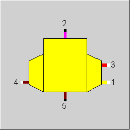
Line connections |
|
|
|
1 |
Oxidizing inlet |
|
|
2 |
Crude gas outlet |
|
|
3 |
Water-/Steam inlet |
|
|
4 |
Coal inlet |
|
|
5 |
Ash extraction |
|
General User Input Values Characteristic Lines Physics Used Displays Example
The component for coal gasification simulates the chemical conversion in the reactor of a coal-to-gas plant under design and off-design conditions.
At the nominal load point, the model returns the adiabatic outlet temperature and the gasification products under consideration of the boundary conditions
For off-design mode, the calculation is carried out in the same way as for the design mode, but with the difference that the load-dependent characteristic lines are used.
For simulating the complete system of "gasifier", a high temperature heat exchanger must be used for describing the reactor wall cooling.
The reactor model permits the simulation of
Solid bed gasifiers can only be described approximately. Because of the low temperature, the shift-balance is not reached and a number of higher hydrocarbons will develop that are not contained in the crude gas library.
The model of the coal gasifier comprises of two sub models:
The description given below restricts itself to the reactor; the high temperature heat exchanger (component 51) is handled analog to the known heat-exchanger components (component 26).
However, an additional radiation characteristic line allows a more realistic consideration of radiant heat transmission.
The reactor model is essentially based on the assumption that the water-gas shift balance
KP(T) = CO H2O/(CO2 H2)
is valid. This is a good approximation for gasifier systems with operating temperatures between 1472 and 1652 °C, so that flue-dust and fluidized bed gasifiers become accessible for a simulation. There are three methods for calculating the shift constants.
Regardless of these simplifications, the calculation of the reactor process requires five more limiting values, which are based on experience or measurements.
These are:
The supplied and the extracted mass flows can be defined in two ways:
In the off-design mode, the same model is used with the difference that
are defined as load-dependent characteristic lines.
The following new result values are output for the gasifier components: RFA, RFAST, EQRAT
|
DP12N |
Absolute pressure loss (nominal) |
|
ROCN |
Oxygen/Carbon ratio |
|
RWM4N |
Water-Steam/Coal ratio |
|
RFLAS |
Fly ash ratio |
|
RCFA |
ratio C (fly ash) /C (fly ash and ash) |
|
RGASN |
Efficiency of carbon gasification (nominal) |
|
RCCH4N |
C in CH4/C total ratio (nominal) |
|
RSH2SN |
S in H2S/S total ratio (nominal) |
|
CWGS |
Water-gas shift constants |
|
TFRE |
Freezing temperature of the shift reaction |
|
TASHE |
Ash temperature |
|
FMODE |
Calculation mode Like in Parent Profile (Sub Profile option only) Expression =0: GLOBAL =1: local off-design |
|
FSFT |
Calculation of the shift reaction Like in Parent Profile (Sub Profile option only) Expression =1: calculate shift reaction at temperature T2 =2: calculate shift reaction at TFRE =3: calculate shift reaction at input CWGS |
|
FMAS |
Switch for calculation type of the mass balance Like in Parent Profile (Sub Profile option only) Expression =1: Input of 1 mass flow from M1/M2/M3/M4 =2: Input of 3 mass flows from M1/M2/M3/M4 |
|
M1N |
Mass flow of oxidizing fluid (nominal) |
The parameters marked in blue are reference quantities for the off-design mode. The actual off-design values refer to these quantities in the equations used.
Generally, all inputs that are visible are required. But, often default values are provided.
For more information on colour of the input fields and their descriptions see Edit Component\Specification values
For more information on design vs. off-design and nominal values see General\Accept Nominal values
|
ROC |
Oxygen to carbon ratio |
|
RWM4 |
Steam to coal ratio |
|
RCWGS |
Calculated water gas shift constant |
|
RGAS |
Carbon gasification |
|
RCCH4 |
CH4-production (C in CH4 / C total) |
|
RSH2S |
H2S-production (S in H2S / S total) |
|
NCVCG |
Net calorific value of natural gas at 0°C |
|
NCVCOAL |
Net calorific value of coal at 0°C |
|
RQCGC |
Cold gas efficiency (Latent heat output/input) |
|
RFA |
Ratio fuel mass flow to air mass flow |
|
RFAST |
stoichiometric ratio of fuel mass flow to air mass flow (i.e. the ratio required for complete combustion) |
|
EQRAT |
equivalence ratio = RFA / RFAST An equivalence ratio EQRAT greater than 1 always indicates a fuel excess in the fuel-oxidant mixture, i.e. more fuel than required for a complete combustion (stoichiometric reaction), irrespective of which fuel and which oxidant are used, whereas ratios smaller than 1 indicate a lack of fuel or an equivalent oxidant excess in the mixture. |
|
Characteristic line 1, CCSL: C-degree of the gasification characteristic line RGAS/RGASN = f (M1/M1N) |
|
X-axis 1 M1/M1N 1st point |
|
Characteristic line 2, CCH4: CH4-conversion-characteristic line RCCH4/RCCH4N = f (M1/M1N) |
|
X-axis 1 M1/M1N 1st point |
|
Characteristic line 3, CH2S: H2S-conversion-characteristic line RSH2S/RSH2SN = f (M1/M1N) |
|
X-axis 1 M1/M1N 1st point |
|
All cases |
||
|
|
Elementary components ---------------------------------------
Calculation of the elementary mass portions EL4 C, H, O, N, S, CL, AR, ash, KLKof coal
Calculation of the elementary mass portions EL1 C, H, O, N, S, CL, AR, ash, KLKof the oxidant
Different load cases ------------------------------ if FMAS = 1 (Calculation of the mass flows through ROCN and RWM4N), then { M3M4= RWM4N M1M4 = f(ROCN) }
if FMAS = 2 (Input of the mass flows through M1, M3, M4), then { M3M4 = M3/M4 M1M4 = M1/M4 }
if FSFT=1 (shift constant at T2), then { SH = A*EXP(-B/(T2+273.15)) }
if FSFT =2 (shift constant at TFRE), then { SH = A*EXP(-B/(TFRE+273.15)) }
if FSFT =3 (shift constant for CWGS), then { SH = CWGS }
Calculation of the components in crude gas and ash -------------------------------------------------------------------------------------------------
Ash formation ZA= EL4_ASH*RFLAS SA = EL4_ASH*(1-RFLAS)
C-gasification CV = EL4_C * RGASN
carbon remaining in crude gas and ash ZC = EL4_C*RCFA* (1-RGASN) SC = EL4_C*(1-RCFA)*(1-RGASN)
CH4-portion in crude gas ZCH4= EL4_C*RCCH4N*MCH4/MC
H2S-portion in crude gas ZH2S = EL4_S * RSH2SN *MH2S/MS ZCOS = EL4_S * (1-RSH2SN)*MH2S/MS
HCL-portion in crude gas ZHCL = EL4_CL* MHCL/MCL
N2-portion in crude gas ZN2= EL4_N+EL1_N*M1M4
AR-portion in crude gas ZAR= EL4_AR+EL1_AR*M1M4
O2-portion in crude gas ZO2= 0
Solution of the reactions equation ------------------------------------------------------ The 4 components in the crude gas ZCO2 ZCO ZH2 ZH2O
are calculated from the shift balanceSH = CO2*H2/(CO*H2O), the C-balance, the H-balance, the O-balance
Calculation of the crude gas components ------------------------------------------------------ ZSUM = ZN2+ZO2+ZAR+ZH2O+ZCO2+ZCO+ZCOS+ZH2+ZH2S+ZCH4+ZHCL+ZC+ZA
d2tod4 =ZSUM
XN2 = ZN2/ZSUM XO2 = ZO2/ZSUM etc.
Calculation of the ash components ----------------------------------------------------- ASUM = SA+SC
M5/M4 =ASUM
A = SA/ASUM C = SC/ASUM
Equations for pressure ==============================
F = 1.0 F = (M1/M1N) ** 2 for GLOBAL = off-design
DP12 = DP12N * F
P2 = P1 - DP12 P4 = P1 P3 = P1 P4 = P5
Calculations for enthalpy ===========================
T5 = TASHE H5 = f(P5,T5) M2 = M1 + M3 + M4 - M5
H2 = (M1 * H1 + M3 * H3 + M4 *(H4+NCV4) - M5 * H5)/M2 - NCV2
Calculations for mass flow ============================
M1 = M1M4 * M4 M2 = M2M4 * M4 M3 = M3M4 * M4 M5 = M5M4 * M4
|
|
 |
Display Option 1 |
Click here >> Component 50 Demo << to load an example.