EBSILON®Professional Online Documentation


|
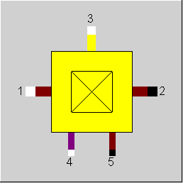
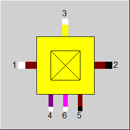
Line connections |
|
|
|
1 |
Flue gas or air inlet |
|
|
2 |
Hot flue gas outlet |
|
|
3 |
Secondary air (cooling) inlet |
|
|
4 |
Fuel inlet |
|
|
5 |
Ash extraction (if available) |
|
|
6 |
Additional flue inlet (if available) |
|
General User Input Values Physics Used Displays Example
The duct burner is intended as an additional combustion after the gas turbine and before the first superheated bundle of the waste heat boiler. The component calculates the adiabatic combustion temperature and the air ratio based on a given fuel and primary air mass flow (exhaust gas flow of the gas turbine). The secondary air mass flow is not involved in the combustion but it constitutes a mixture with the primary combustion gases. The component works adiabatically.
It is recommended to control the O2-concentration in the exhaust gases coming from the duct burner. This value must not drop below 3%. Also, the air ratio must be controlled, because it is calculated. This value must not drop below 1.1.
The NOX concentration at the outlet can be specified via a kernel expression. This is controlled via the flag FNOCON:
The flag FCON controls whether the concentration (NOx) is given as a mol fraction or as a standardized mass fraction (mg/Nm³).
Note:
As of Release 9.00, there is a new flag FETAB. It serves to specify whether the heat loss is to be related to the total heat or only to the fuel heat.
(Before, in the case of fuel mass flows < 10^-4 kg/s the loss was related to the fuel heat, but in the case of greater ones to the total heat.)
For this component, M3N and M4N have been added as nominal values to allow access in scripts or expressions. The Ebsilon calculation kernel does not use these values.
In this component, the new combustion algorithm is applied where not only the combustible substances contained at the fuel inlet (4) but also those contained in the air and flue
gas supply respectively (1) are burned. This enables a post-combustion of the CO contained in the inflowing exhaust gas in particular.
The component always performs a complete combustion.
The model is based on an assumption of a complete combustion between
and the subsequent mixing with the secondary air mass flow (line 3).
Mass balances and compositions on the output lines are calculated as follows
The composition of the flue gas in the combustion calculation is based on the composition of the incoming gases (this is normally the waste gas of the gas turbine), the fuel composition and the additional air under consideration of the ash balance.
The outlet enthalpy of the hot gas results from a balance based on the first fundamental principle considering
The outlet pressure P2 results from the inlet pressure and the pressure loss
The pressure P3 (cooling air) must always be higher than or equal to P1.
The combustion efficiency ETAB can optionally be related to the total heat or only to the fuel energy.
A calculation of the chemical equilibrium based on the NASA code used in the Gibbs reactor (Component 134) can be carried out instead of a combustion calculation. The new flag FOP is used to switch over:
The equilibrium is calculated at the temperature and the pressure of the exhaust gas. However, it is possible to increase the reaction temperature by means of the specification value DTREACT (DTREACT>0) or to decrease it (DTREACT<0). A decrease can make sense if an equilibrium cannot be achieved because the sojourn time in the reactor is too low. However, this feature is only available if the exhaust gas temperature is specified (as a default value or from outside), not when the adiabatic combustion temperature is used (see section "Adiabatic outlet temperature"
Ionization is not considered in Component 41.
As usually no slag accumulates in the operation with gas, the slag outlet (Pin 5) is now hidden by default. If needed, it can be shown again in the tab “Ports” of the Component Properties.
As previously with Components 21 and 90, there is now a second fuel pin in Components 22 and 41 too for e.g. displaying an oil firing. By default, however, it is hidden. If needed, it can be shown again in the tab “Ports” of the Component Properties.
Previously, the cooling air (Pin 3) was added to the exhaust gas only downstream of the combustion in order to decrease its temperature. It did not take part in the combustion as a rule. When it was impossible to provide enough oxygen for the combustion via Pin 1, an error message was output.
In Release 15, it is possible to have the cooling air participate in the combustion too. For this purpose, there is a flag FCOOLAIR:
The cooling water mass flow has to be specified externally in either case.
For the given total air mass flow (or the quantity of fuel), the given air ratio and the given final temperature of hot gas, this component calculates the necessary mass flow of fuel (or the total air mass flow) and the ratio of the primary air mass flow of the total air mass flow. The component does not work adiabatically. The released quantity of heat is fed to a line connection.
For the given fuel mass flow (or primary air mass flow) and the given air ratio, this component calculates the necessary primary air mass flow (or the fuel mass flow) and the final temperature of the hot gas. This is a mixture of the primary air, which has reached adiabatic combustion temperature, and the secondary air, which only serves the jacket cooling and is not involved in the combustion. The component works adiabatically.
In this component always a complete combustion takes place. However, it is possible by setting the specification value ETAB (combustion efficiency) that the generated heat is not utilized completely (i.e. a heat loss takes place). If one wants to take into account the unburnt portion in the slag or in the flue gas, the component 21 (combustion) or 90 (combustion chamber in geometric boiler mapping) are to be used.
|
DP12N |
Pressure loss (nominal) |
|
FOP |
Operation mode
Like in Parent Profile (Sub Profile option only) Expression =0: Combustion
|
|
DTREACT |
Temperature difference between reaction- and exhaust temperature (FOP=1) |
|
DES |
Desulfurization (deprecated) |
|
FETAB |
Flag to define basis for ETAB Like in Parent Profile (Sub Profile option only) Expression =0: Heat loss based on total heat =1: Heat loss based on fuel heat only |
|
ETAB |
Combustion efficiency (referring here only to heat loss, no unburnt fuel) |
|
RFLAS |
Fly ash by total ash ratio |
|
TASHE |
Temperature of the extracted ash |
|
FMODE |
Calculation mode Like in Parent Profile (Sub Profile option only) Expression =0: GLOBAL =1: Local off-design =-1: Local design |
|
FCON |
Flag for interpreting NOCON Like in Parent Profile (Sub Profile option only) Expression =1: Molar fraction, (related to reference O2 concentration) =2: Standardized weight ratio at reference O2 concentration The difference between FCON=1 and FCON=2 is the fact that for FCON=2 you have to specify some kind of "density" for the pollutant fraction, i.e. mass of pollutant per volume of flue gas (therefore the dimension mg/Nm³). If you divide this density by the density of the pure pollutant, you get the corresponding molar fraction. In the implementation, the case FCON=2 is traced back to FCON=1, using a constant density of 2.05204 kg/m³ for NOx (independent of NOSPL). |
|
FNOCON |
Flag for the calculation of NOx concentration Like in Parent Profile (Sub Profile option only) Expression =0: By specification value NOCON =1: By function ENOCON |
|
NOCON |
NOx concentration in the exhaust gas (wet molar fraction at reference oxygen concentration) Hint: To reproduce the value NOCON in the exhaust gas pipe, you have to change the reference oxygen concentration in the model settings to the volume fraction of oxygen in the exhaust gas pipe and change the properties of the value cross to display mol fraction. NOCON will be the sum of XNO and XNO2. As this calculation is performed iteratively, the value is reached only approximately. |
|
ENOCON |
Function for concentration of NOx in exhaust gas |
|
NOSPL |
NO-Split (volume portion of the NO by the total NOx) NO-Split (NO/(NO+NO2) (molar fraction)) |
|
FCOOLAIR |
Usage of cooling air (pin 3) Like in Parent Profile (Sub Profile option only) Expression =0: For cooling only, no combustion |
|
FVALNCV |
Net calorific value validation (deprecated) Like in Parent Profile (Sub Profile option only) Expression =0: Net calorific value taken from the line (fixed) =1: Net calorific value taken from the pseudo measurement point (can be validated) =2: Net calorific value given by enthalpy on control inlet 6 |
|
IPS |
Index for pseudo measurement point |
|
M1N |
Primary mass flow (nominal) |
|
M3N |
Secondary mass flow (nominal) |
|
M4N |
Fuel mass flow (nominal) |
The parameters marked in blue are reference quantities for the off-design mode. The actual off-design values refer to these quantities in the equations used.
Generally, all inputs that are visible are required. But, often default values are provided.
For more information on colour of the input fields and their descriptions see Edit Component\Specification values
For more information on design vs. off-design and nominal values see General\Accept Nominal values
|
All cases |
||
|
ALAM=ALAMN DES=DESN ETAB=ETABN RFLAS=RFLAN given { NCV4 net calorific value of fuel M1i/M1 primary air analysis (weight parts) M3i/M3 secondary air analysis (weight parts) M4i/M4 analysis of fuel (weight parts) with i=1..m m = maximum number of elements } For any type of fuel according to elemental combustion { M2i (----------) M2 M4i M1i = f( (--------), (--------),M1, M4, DES, RFLAS) M4 M1 M4i M1i ALAM= f( (--------), (--------),M1, M4, DES, RFLAS) M4 M1 } if GLOBAL = off-design, then { F = (M1/M1N) ** 2 } else { F = 1.0 } DP12 = DP12N * F Point B: combustion chamber outlet before mixing with secondary air stream M3 PB = P1 - DP12 QB = Q1 + Q4 + M4 * NCV4 MB = M1 + M4 HB = QB/MB TB = f (PB, HB) for gaseous and liquid fuels { M5 = 0 P5 = 0 T5 = 0 H5 = 0 Q5 = 0 } for solid fuels { MASH mASH = ---------------- M4 MLIME mLIME=----------------- M4 mAL = mASH + mLIME RASH = mASH /mAL RLIME= mLIME /mAL M5 = mAL* M4 * (1 - RFLAS) P5 = P4 T5 = TASHE H5 = f(P5, T5) Q5 = M5 * H5 } M2 = M3 + MB - M5 M2i M3i MBi-M5i (------) = [(-------)*M3 + (---------------) * (MB-M5)] / M2 M2 M3 MB-M5 with i=1..m m = maximum number of elements P2 = PB QI = Q3 + QB - Q5 heat input QC = QI * ETAB QL = QI - QC H2 = QC/M2 T2 = f(P2, H2) Q2 = M2 * H2 (M1/M4) from elemental combustion calculation M4 = M1/ (M1/M4) P1 = P4 |
||
 |
Display Option 1 |
Click here >> Component 41 Demo << to load an example.