EBSILON®Professional Online Documentation


|
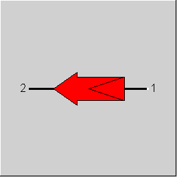
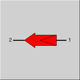
Line connections |
|
|
|
1 |
Signal input |
|
|
2 |
Signal output |
|
General User Input Values Characteristic Lines Physics Used Displays Example
This component is used to model logical links within a model. A typical application example is the equation of two mass flows.
Logic lines are to be drawn from the two ports of the value transmitter to any other lines of the model. The value transmitter then takes a value from the line connected to the input (which one is determined by the FIN switch) and passes it to the line connected to the output. Which value is set on the output line is determined by the FOUT switch. In case of a simple transmission, FIN and FOUT will define the same quantity.
It is possible not to pass the input value directly one-to-one, but to modify it:
The switch FTRANS is used to set whether
The multiplication factor MUL is not taken into account if characteristic C2 is used.
Multiplication by a constant transfer factor (MUL) or addition of a constant offset (OFFSET)
The FOFFSET flag is used to control how these act:
FOFFSET = 0: absolute for output signal:
(OUT - OFFSET) / REFOUT= MUL * (IN / REFIN)
FOFFSET = 1: related to REFOUT for output signal:
OUT / REFOUT - OFFSET= MUL * (IN / REFIN)
FOFFSET = 2: absolute for input signal:
OUT / REFOUT= MUL * ((IN - OFFSET) / REFIN)
FOFFSET = 3: related to REFIN for input signal:
OUT / REFOUT= MUL * (IN / REFIN - OFFSET)
Using the characteristic C2 and the additive offset (OFFSET)
If the OFFSET is used in connection with the characteristic C2 (FTRANS=2), a corresponding shift of the input value of the characteristic occurs at FOFFSET=2 or =3:
FOFFSET = 0: absolute for output signal:
(OUT - OFFSET) / REFOUT = C2 (IN / REFIN)
FOFFSET =1: related to REFOUT for output signal:
OUT / REFOUT - OFFSET = C2 (IN / REFIN)
FOFFSET =2: absolute for input signal:
OUT / REFOUT = C2 ((IN - OFFSET) / REFIN)
FOFFSET =3: related to REFIN for input signal:
OUT / REFOUT=C2 (IN / REFIN - OFFSET)
It is also possible to transfer the derived variables temperature and volume flow. Since these are not basic quantities for the system of equations, they are mapped internally to enthalpy or mass flow. The temperature transfer is implemented as enthalpy transfer, the volume flow transfer as mass flow transfer with corresponding coefficients.
If the net calorific value or the material composition is used as input signal, the same quantity must be used at the outlet. The transmission is unchanged, i.e. neither the multiplication factor nor the characteristic curve is taken into account. The transfer of the material composition is always complete, i.e. for all substances.
The component also offers the possibility of damping the transmission. This can be useful for convergence problems.
The transfer factor MUL can be displayed graphically in the model. For this purpose, the flag "Show value transmitter factors" must be activated in the "General settings" (main menu) on the sheet "Display".
When using the characteristic curve, "CL" appears instead of the factor.
If the signal transformer is switched off, it is displayed dimmed, "off" appears as factor.
Special case MUL="empty"
For compatibility with old EBSILON®Professional versions, the reciprocal value of the input signal is transmitted if the specification value MUL is empty. For the sake of clarity, however, such constructions should be carried out with the calculation module (component 77) which is available in the meantime.
Alternatively, a matching polynomial or kernel expression can be used, either as a correction factor for the transmission factor (FADAPT=1 or =-1) or as a calculation for the output value (FADAPT=2 or =-2).
The FWARN switch allows to activate or deactivate a warning if the signal transformer has reached the lower or upper limit.
LLIM / ULIM- Lower / Upper limit
LLIM / ULIM limits the result value downwards or/and upwards.
LLIM < ULIM --> OUT > LLIM and OUT< ULIM --> L2 = OUT
OUT < LLIM L2 = LLIM --> Output of a warning!
OUT > ULIM L2 = ULIM --> Output of a warning!
LLIM > ULIM --> L2 = OUT
LLIM = ULIM --> L2 = OUT
Transfer of the calorific value
When transmitting the material composition (FIN=FOUT=13), the calorific value is automatically transmitted as well, so that it is no longer necessary to place a second transmitter for the calorific value next to it. However, a separate transmission of the calorific value (FIN=FOUT=14) is still possible, since fluids with different compositions may well have the same calorific value.
With FIN=102 and FOUT=102, it is possible to transfer the sum of enthalpy and calorific value instead of enthalpy. This makes it easier to map the energetic relationships in chemical reactions. Note: The lower calorific value related to a reference temperature of 0°C is always used for this purpose.
Transmission of the Electric Current
In the case of the value transmitter, a transmission of the electric current is possible as well by means of FIN=15 and FOUT=15 respectively. Internally, the enthalpy is transmitted in this case; however, it is provided with appropriate pre factors so that the current remains the same (as long as MUL=1 and OFFSET=0), or it is provided with appropriate factors or offset.
A transmission of the current to other variables and vice versa is possible too.
Transferring the composition
The composition can also be transferred from a water/steam line to a classic line of the air, flue gas, coal, etc. type. This then contains 100% H2O.
Power transfer
It is also possible to transfer the power (heat flow) in fluid streams. In this case, the enthalpy is transferred with the corresponding mass flows as coefficients.
For data reconciliation, it should be noted that for error propagation of uncertainties in the mass flows, these would have to be treated as variables instead of coefficients, which is possible, for example, with component 77 (calculation module).
Note - Characteristic Lines Related to Nominal Temperature
For the component 36 there is a characteristic line, which refers to a nominal value of temperature. This is the characteristic line C2 for the outlet temperature of the value transmitter, which provides the ratio IN/REFIN und/oder OUT/REFOUT.
Unfortunately, such temperature ratios depend on the selected system of units. In contrast to other units where the conversion is effected only via a certain factor and therefore has no effects on the quotient, in the temperature conversion there is an additive offset whereby the value of the quotient changes.
There is the possibility (to specify this characteristic line in other units (°F, K).
Users who prefer other unit systems for the temperature (e.g. ° F, K) must set the selected temperature unit in the new flag FTNI, because Ebsilon calculates internally with the temperature unit ° C.
Depending upon the comparison of two thermodynamic values, a signal value can be transmitted either from input 1 or from input 2 to output 3. All the 5 thermodynamic values P/T/H/M/Q can be comparative values. An index of function defines whether the comparison takes place between the signal entry 4 and the decision value set to specification value or directly between the two signal entries 1 and 2. For each signal input, an index of transmissions defines whether the related physical value of the signal input is multiplied with a proportionality factor or whether a fixed value is transmitted.
Depending on the comparison of two thermodynamic values either a flow rate of input 1 or of input 2 can be transmitted to output 3. All five thermodynamic values P/T/H/M/Q can be comparative values.
Enables the linking of two input signals to one output signal.
|
FIN |
Flag for the value to be used as input signal: |
|
FOUT |
Flag for the value to be used as output signal |
|
MUL |
Multiplier |
|
REFIN |
Reference value for the input value The value on the input line is divided by this value before further processing. This is especially helpful when using a characteristic line (FTRANS=2). |
|
REFOUT |
Reference value for the output value The value that results from the calculation is multiplied with this value, before it is transferred to the output line. When using a factor (FTRANS=1) it is recommended to leave the value to 1. |
|
FTNI |
Unit used for calculation of IN/REFIN and/or OUT/REFOUT in C2 =0: Celsius |
|
FTRANS |
Flag for the modification of the input signal =1: Multiplication with the factor MUL |
|
FOFFSET |
Flag for usage of OFFSET See General for details |
|
OFFSET |
Additive Offset With FOFFSET=0 the summand has the dimension of the (absolute) output quantity. |
|
FDAMP |
|
|
FADAPT |
Flag for using the adaptation polynomial / adaptation function =0: Not used and not evaluated =1: As correction factor : signal transfer factor = [signal transfer factor * polynomial] =2: As a replacement: signal transfer factor = polynomial =1000: Not used but ADAPT evaluated as RADAPT (Reduction of the computing time) = -1: As correction factor : signal transfer factor = [signal transfer factor *adaptation function] = -2: As a replacement: signal transfer factor = adaptation function = -1000: Not used but EADAPT evaluated as RADAPT (Reduction of the computing time) |
|
EADAPT |
Adaptation function |
|
LLIM |
Lower limit |
|
ULIM |
Upper limit |
|
FWARN |
Warning in case of activated limits =0: no warning =1: warning |
Generally, all inputs that are visible are required. But, often default values are provided.
For more information on colour of the input fields and their descriptions see Edit Component\Specification values
For more information on design vs. off-design and nominal values see General\Accept Nominal values
|
Characteristic line C2: OUT / REFOUT = f ( IN / REFIN ), value transfer characteristic |
|
X-axis 1 IN / REFIN 1st point |
|
All cases |
||
|
for transmission with a factor OUT IN ------------- = MUL * ------------ (1) REFOUT REFIN
for transmission with a factor MUL und additive OFFSET ( OUT - OFFSET) IN for transmission with a characteristic line OUT IN ------------- = f( ------------ ) (3) REFOUT REFIN |
||
 |
Display Option 1 |
Click here >> Component 36 Demo << to load an example.