
|
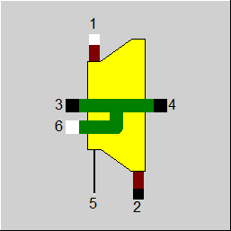
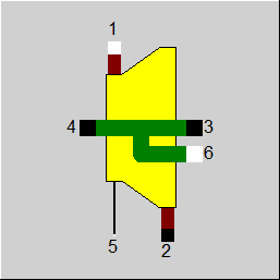
Line connections |
|
|
|
1 |
Flue gas inlet |
|
|
2 |
Flue gas outlet |
|
|
3 (6) |
Shaft connection for compressor Shaft / "None" If shaft outlet 3 should be active, then that is Shaft outlet 6 = "NONE" to be set. |
|
|
4 |
Shaft connection for generator |
|
|
5 |
Control inlet for isentropic efficiency (as H) |
|
|
6 |
Shaft connection for generator Shaft / "None" If shaft outlet 6 should be active, then that is Shaft outlet 3 = "NONE" to be set. |
|
General User Input Values Characteristic Lines Physics Used Displays Example
This module represents the expander part of a gas turbine. The inlet and outlet pressures have to be defined. Normally this is defined by the compressor of the gas turbine on the one hand and the outlet pressure on the other hand. Else, component 33 (pastille) must be used for specification.
A gas turbine system can be modelled together with the modules 22 (combustion chamber) and 24 (compressor). But the difficulty is imitating the influences of shell-, shaft- and of blade foot cooling adequately enough. These uncertainties can be avoided by using the macro-component 40 (Gas Turbine (macro)).
If the power requirement at the outlet for the compressor is higher than the power generated by this component, an error message is generated in which the required and supplied power are also displayed.
In the past, the second shaft connection on component 23 (steam turbine) was a shaft input. This made it possible to connect several turbine discs in series for component 23, so that the shaft power was added together.
The reverse case of power splitting for component 23 could not be represented graphically in the past. However, there was a switch FQ (power flow) for the calculation, with which the calculation could be changed, but with the drawback that the graphical representation then did not match the calculation.
The reverse power flow can now also be displayed graphically. Shaft connection 6 should be used for this.
To enable a corresponding visualisation, the previously existing connection has been hidden and the new connection has been positioned in the same place. Usually, either the input or the output is used and the unused connection should then be hidden. In principle, however, the software also allows both connections to be used simultaneously.
As with the previous second shaft connection, the power must also be specified on the new connection. The turbine can only calculate the power at the main shaft output.
The new connection means that the FQ switch is now superfluous. However, it is still available for compatibility reasons, but has been labelled as ‘obsolete’.
In addition, a comment message may be displayed to indicate the possibility of using the new connection. The switch also reverses the calculation direction for the new shaft connection.
A new result value QSHAFT has been implemented for component 23 (also for component 6, 58), which outputs the shaft power generated in the component, regardless of which connections it is distributed to or which shaft power is added.
Previously, the simplified formula for ideal gases was used for calculating the Stodola pressure in this component. As the flue gas is calculated as ideal gas by default, this approximation is definitely justified.
Meanwhile, however, Ebsilon allows to activate a real gas correction for the flue gas. As in this case, the application of the ideal gas Stodola formula is inconsistent, the more detailed formula for real gases is used now.
An option to switch over between ideal gas and real gas formula as in Component 6 is not provided here. In Component 6, it only exists for historical reasons anyway and should not be used in new models.
See also: Part-load - Steam Turbine
Logic inlet (Connection point 5) for controlling component properties
(see also : Editing components --> Ports)
To make component properties like efficiencies or heat transfer coefficients (variation quantity) accessible from the outside (for control or reconciliation) it is possible to place the respective value on an auxiliary line as an indexed measured value (specification value FIND). In the component, the same index must then be entered as specification value IPS.
It is also possible to place these values on a logic line that is directly connected to the component (please see FVALETAI=2, Variation variable ETAIN, Dimension: Enthalpy).
The advantage is that the allocation is graphically visible, and errors (e.g. when copying) are thus avoided.
The activation of this logic line can also be made conditional on the mode of calculation. This way, this feature can also be used for designs without having to switch manually all the time.
For this, the flag FVALETAI features the settings
· FVALETAI=4: use logic line in design mode, use specification value in off-design
· FVALETAI=5: use specification value in design mode, use logic line in off-design
This option is available for Components 2, 6, 8, 13, 18, 19, 23, 24, and 94.
Implementing a load-independent mechanical loss (QLOSSM) (see Release-Notes for Release 12)
The sequence in which the proportional and the constant fraction are considered depends on the direction of the flow of energy.
If both a mechanical efficiency ETAMN and a constant loss QLOSSM are specified, the two are combined as follows:
Q_net = Q_gross *ETAMN - QLOSSM
The result value QLOSS comprises the entire (load-independent and load-dependent) loss
QLOSS = Q_gross – Q_net
The result value ETAM contains both fractions (as in the case of component 6), as ETAM is defined by
ETAM = Q_net / Q_gross
If a QLOSSM > 0 is specified, ETAM thus no longer equals ETAMN but is accordingly smaller (by QLOSSM/heat supply).
Result Value M1M1N
The ratio of the current mass flow M1 to its design value M1N is now output as result value M1M1N. As this is the x-value for the efficiency characteristic line, the creation of the characteristic line is thus facilitated.
Result Value MCORR
There is now a result value MCORR that specifies which mass flow would flow through the expander under standard conditions. The calculation is carried out according to https://en.wikipedia.org/wiki/Corrected_flow:
MCORR = M1 * SQRT(T1[K]/TNORM) / (P1/PNORM)
with TNORM = 288.15 K and PNORM = 1.01325 bar.
|
FP1 |
Inlet pressure =0: P1N=P1NSET =1: P1 specified from outside |
|
P1N |
Inlet pressure (nominal) |
|
FVALETAI |
Validation of the isentropic efficiency =0: ETAIN used without validation =1: (Deprecated) IPS used instead of ETAIN (validable) =2: ETAIN given by enthalpy on control inlet 5 =4: Enthalpy on control inlet 5 used in design, specification value ETAIN in off-design =5: Specification value ETAIN used in design, enthalpy on control inlet 5 in off-design |
|
ETAIN |
Isentropic efficiency (nominal) |
|
IPS |
Index on pseudo measurement point |
|
ETAMN |
Mechanical efficiency (nominal) |
|
QLOSSM |
Mechanical loss (constant fraction) |
|
FCHR |
Characteristic line type =0: ETAI/ETAIN=f(M1/M1N) =-1: Power specification =-2: H2 given |
|
FQ |
Flag for power flow at point 3 =0: Shaft inlet to of turbine HP side (Shaft inlet of a Q-supplier) =1: Shaft outlet to of turbine HP side (Shaft outlet for e.g. compressor) |
|
FSTO |
Flag for using the Stodola-equation for calculating the inlet pressure in off-design mode =0: simplified form (without dependency on the outlet pressure) =1: detailed form (dependent on the outlet pressure) The simplified form can be used, when the outlet pressure remains constant (e.g. a relaxation is always done to the ambient pressure). |
|
FMODE |
Flag for calculation mode =0: GLOBAL =1: Local off-design = -1: Local design |
|
FADAPT |
Flag for adaptation polynomial ADAPT/ adaptation function EADAPT =0: Not used and not evaluated =1: Correction [ETAI = ETAIN * Char Line * polynomial] =2: Replace [ETAI = ETAIN * polynomial] =1000: Not used but ADAPT evaluated as RADAPT (Reduction of the computing time) = -1: Correction [ETAI = ETAIN * Char Line * adaptation function ] = -2: Replace [ETAI = ETAIN * adaptation function ] = -1000: Not used but EADAPT evaluated as RADAPT (Reduction of the computing time) |
|
EADAPT |
Adaptation function |
|
M1N |
Inlet mass flow (nominal) |
|
T1N |
Turbine inlet temperature TIT (nominal) |
|
P2N |
Outlet pressure (nominal) |
The parameters marked in blue are reference quantities for the off-design mode. The actual off-design values refer to these quantities in the equations used.
Generally, all inputs that are visible are required. But, often default values are provided.
For more information on colour of the input fields and their descriptions see Edit Component\Specification values
For more information on design vs. off-design and nominal values see General\Accept Nominal values
|
ETAI |
Isentropic efficiency |
|
ETAM |
Mechanical efficiency (including QLOSSM) |
|
RHO2 |
Specific weight of exhaust gas |
|
VM2 |
Volume flow of exhaust gas |
|
ETANIR |
Used value for nominal isentropic efficiency |
|
ETACL |
Efficiency due to characteristic |
|
RADAPT |
Result of ADAPT / EDAPT |
|
MCORR |
Corrected mass flow |
|
QSHAFT |
Generated mechanical power |
|
M1M1N |
Relative cold side mass flow |
|
Characteristic line 1: isentropic efficiency characteristic line ETAI/ETAIN = f (M1/M1N) |
|
X-axis 1 M1/M1N 1st point |
|
All cases |
||
|
(ETAI/ETAIN) = f (M1/M1N) corresponding to the characteristic line ETAI = (ETAI/ETAIN) * ETAIN P2 taken from line 2 M2 = M1 S1 = f (P1, T1) T2S = f (P2,S1) H2S = f (P2,T2S) DHS = H1 - H2S DH = DHS * ETAI H2 = H1 - DH T2 = f (P2, H2) Q2 = M2 * H2 Q3 : power input or power output Q= (H1*M1 - H2*M2) * ETAMN if FQ=0 FAC= 1 if FQ=1 FAC=-1 H4 = (Q + H3*M3 * FAC)/M4 if GLOBAL = design, then { F = 1.0 } if GLOBAL = off-design, then { F=according to Stodola's law } See also: Part-load - Turbine P1 = P1N * F |
||
 |
Display Option 1 |
 |
Display Option 2 |
Click here >> Component 23 Demo << to load an example.