EBSILON®Professional Online Documentation


|
Line connections |
|
|
|
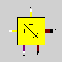
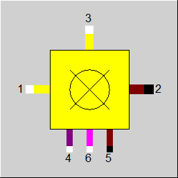
1 |
Primary air inlet for combustion |
|
|
2 |
Hot flue gas outlet |
|
|
3 |
Secondary (cooling) air inlet |
|
|
4 |
Fuel inlet |
|
|
5 |
Extraction of ashes (if available) |
|
|
6 |
Additional fuel inlet (if available) |
|
General User Input Values Physics Used Displays Example
Component 22 was created initially as a calculation module for the combustion chamber of a gas turbine. The combustion calculation provides the adiabatic combustion temperature. Only the primary air mass flow takes part in the combustion. The secondary air flow only cools the furnace wall and mixes with the combustion gases at the end of the combustor. Connection 2 of the module is thus a flue gas mixing temperature.
The component can also be used as the standard combustion chamber of a boiler. The secondary air can be taken as zero. The flue gas temperature is thus the temperature before the first superheated bundle. Contrary to component 21, additional heating bundles in the flue gas are not possible. These have to be modelled separately e.g. with the modules 25 and/or 26.
Depending upon the flag FALAM, the air ratio is selectively
Normally, the fuel is gas or oil, but coal is also permitted. For this reason, the ash content can be manipulated. The ash content of the coal is removed through the ash extraction. The specification value "flying ash content" defines the amount of ash contained in the flue gas, which will be extracted by the boiler as the flying ash and hence will not be removed through the ash extraction.
Burnable substances in the air inlet are included in the combustion.
With this component a complete combustion always takes place. However, it is possible by setting the specification value ETAB (combustion efficiency) that the generated heat is not utilized completely (i.e. a heat loss takes place). If one wants to take into account the unburnt portion in the slag or in the flue gas, the component 21 (combustion) or 90 (combustion chamber in geometric boiler mapping) are to be used.
The heating value of the flue gas is calculated from the composition.
The NOX concentration at the outlet can be specified via a kernel expression. This is controlled via the flag FNOCON.
The flag FCON controls whether the concentration is given as a mole fraction or as a standardized mass fraction (mg/Nm³).
A calculation of the chemical equilibrium based on the NASA code used in the Gibbs reactor (Component 134) can be carried out instead of a combustion calculation. The new flag FOP is used to switch over:
The concentrations for CO and NOx are set to the specified values after the calculation of the equilibrium (this also applies if the specified value is 0!). If, however, the values for CO and NOx calculated in the equilibrium are to be retained, the flags FCOCON and FNOCON respectively must be set to -1.
The specification of the reaction rates for the direct desulfurization, however, cannot be combined with the calculation of the equilibrium.
The distribution of the ash and of the unburned matter is carried out according to RFLAS and UBASH.
The equilibrium is calculated at the temperature and the pressure of the exhaust gas. However, it is possible to increase the reaction temperature by means of the specification value DTREACT (DTREACT>0) or to decrease it (DTREACT<0). A decrease can make sense if an equilibrium cannot be achieved because the sojourn time in the reactor is too low. However, this feature is only available if the exhaust gas temperature is specified (as a default value or from outside), not when the adiabatic combustion temperature is used (see section "Adiabatic outlet temperature"
Ionization is not considered in Component 22.
As usually no slag accumulates in the operation with gas, the slag outlet (Pin 5) is now hidden by default. If needed, it can be shown again in the tab “Ports” of the Component Properties.
As previously with Components 21 and 90, there is now a second fuel pin in Components 22 and 41 too for e.g. displaying an oil firing. By default, however, it is hidden. If needed, it can be shown again in the tab “Ports” of the Component Properties.
Previously, the cooling air (Pin 3) was added to the exhaust gas only downstream of the combustion in order to decrease its temperature. It did not take part in the combustion as a rule. When it was impossible to provide enough oxygen for the combustion via Pin 1, an error message was output.
it is possible to have the cooling air participate in the combustion too. For this purpose, there is a flag FCOOLAIR:
The cooling water mass flow has to be specified externally in either case.
|
FMODE |
Calculation mode =0: GLOBAL =1: Local off-design =-1: Local design |
|
FOP |
Operation mode =0: Combustion |
|
FALAM |
Calculation mode for combustion calculation (use of ALAMN) =0: Specify one flow and calculate the other using ALAMN =1: Specify both flows externally = -11: Definition air mass flow (M1), fuel (M4) and Ash extractions externally ( special mode for VDI2048 validation) |
|
ALAMN |
Air ratio (air to air stoichiometric) (nominal) See Lambda definitions |
|
DTREACT |
Temperature difference between reaction and exhaust gas temperature (FOP=1) |
|
DES (deprecated) |
Desulphurization (deprecated) |
|
ETAB |
Un Lost heat fraction of exhaust gas |
|
RFLAS |
Fly ash by total ash ratio |
|
TASHE |
Temperature of ash extraction |
|
FSPECP |
Handling of pressure drop =0: DP12=DP12N*(M1/M1N)**2; DP14=DP45=0 |
|
DP12N |
Pressure drop (nominal) |
|
FCON |
Flag for interpreting NOCON =1: Mole ratio (related to reference O2 concentration) =2: Standardized weight part (at reference O2 concentration) The difference between FCON=1 and FCON=2 is the fact that for FCON=2 you have to specify some kind of "density" for the pollutant fraction, i.e. mass of pollutant per volume of flue gas (therefore the dimension mg/Nm³). If you divide this density by the density of the pure pollutant, you get the corresponding mole fraction. In the implementation, the case FCON=2 is traced back to FCON=1, using a constant density of 2.05204 kg/m³ for NOx (independent of NOSPL). =3: Direct specification of the NOX mass flow rate =4: Direct specification of the NOX mass fraction =5: Direct specification of the NOX mole fraction =6: Specification of the proportion of chemically bound nitrogen in the fuel (i.e. all nitrogen except N2) that is converted into NOx - Direct specification means that the specification value is used directly, without any conversions due to standard conditions, O2 or H2O. |
|
FNOCON |
Calculation of NOx concentration =0: By specification value NOCON =1: By function ENOCON |
|
NOCON |
NOx concentration in the exhaust gas (wet molar fraction at reference oxygen concentration) Hint: To reproduce the value NOCON in the exhaust gas pipe, you have to change the reference oxygen concentration in the model settings to the mole fraction of oxygen in the exhaust gas pipe and change the properties of the value cross to display mole fraction. NOCON will be the sum of XNO and XNO2. As this calculation is performed iteratively, the value is reached only approximately. |
|
ENOCON |
Function for concentration of NOx in exhaust gas function evalexpr:REAL; |
|
NOSPL |
NO-Split (mol ratio of NO to whole NOx, (NO/(NO+NO2)) |
|
FCOOLAIR |
Usage of cooling air (pin 3) =0: For cooling only, no combustion |
|
FVALNCV (deprecated) |
Validation of heat value (deprecated) =1: Heat value taken from the pseudo measurement point (can be validated) |
|
IPS |
Index for pseudo measurement point |
|
M1N |
Mass flow of combustion air (nominal) |
The parameters marked in blue are reference quantities for the off-design mode. The actual off-design values refer to these quantities in the equations used.
Generally, all inputs that are visible are required. But, often default values are provided.
For more information on colour of the input fields and their descriptions see Edit Component\Specification values
For more information on design vs. off-design and nominal values see General\Accept Nominal values
|
All cases |
||
|
All cases ALAM = ALAMN given { For each fuel type, corresponding elemental combustion applies { M5i if off-design, then { Point B: Combustion chamber outlet before mixing with the secondary air mass flow M3 PB = P1 - DP12 QB = Q1 + Q4 + M4 * NCV4 MB = M1 + M4 HB = QB/MB TB = f (PB, HB) Gaseous and liquid fuels { M5 = 0 P5 = 0 T5 = 0 H5 = 0 Q5 = 0 Solid fuel { MAsh mAsh = ---------------- M4 MLIME mLime = ----------------- M4 mAL = mAsh+ mLIME RAsh= mAsh/mAL RLIME=mLIME /mAL M5 = mAL* M4 * (1 - RFLAS) P5 = P4 T5 = TAshE H5 = f(P5, T5) Q5 = M5 * H5 } M2 = M3 + MB - M5 M2i M3i MBi-M5i (------) = [(-------)*M3 + (---------------) * (MB-M5)] / M2 M2 M3 MB-M5 with i=1..m m = max.number of elements P2 = PB QI = Q3 + QB - Q5 heat input QC = QI * ETAB QL = QI - QC H2 = QC/M2 T2 = f(P2, H2) Q2 = M2 * H2 (M1/M4) from elementary combustion calculation M4 = M1/ (M1/M4) P1 = P4 |
||
 |
Display Option 1 |
Click here >> Component 22 Demo << to load an example.