

|
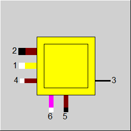
Line connections |
|
|
|
1 |
Air inlet / Humid air inlet |
|
|
2 |
Exhaust gas outlet |
|
|
3 |
Generated thermal heat |
|
|
4 |
Fuel inlet |
|
|
5 |
Ash / Slag extraction (if available) |
|
|
6 |
Additional fuel inlet (if available)
|
|
General Notes User Input Values Characteristic Lines Physics Used Displays Example
Component 21 is a calculation module for combustion chambers and fluidized bed firing. The terminology of the specification values has been adjusted accordingly.
For the combustion chamber of a boiler, the temperature input corresponds to the temperature at the control surface i.e.:
The module executes a combustion calculation. The net calorific value of the fuel and the fuel analysis must be known.
The calorific value of the flue gas is not calculated from the composition, but results from the calorific value of the fuel (which can also be specified independently of the fuel composition) and the combustion efficiency. In the case of gas the combustion efficiency is always 1, so in this case the calorific value in the exhaust gas is zero.
Depending upon the flag FALAM, the air ratio is selectively
The ash content of the coal is removed by the ash extraction. The specification value "flying ash content" defines the amount of ash contained in the flue gas, which will be
extracted by the boiler as the flying ash and hence will not be removed through the ash extraction.
Connection 3 passes the useful heat to the connected component. Together with component 5 (water-steam part of the boiler), this value must be equal to the value at the
connection 5 of component 5, in order to reach the desired steam parameters. This can be done through a control.
Radiation losses can be defined as per EN 12952 or through your own input.
Previously the specification value “C“ had a double function:
When C < 1, C was used for the value of the radiation constant; for C = 1, 2, or 3, the values for oil/gas, hard coal, or lignite were used according to DIN EN 12952.
A new switch FC has been implemented.
The NOX and CO concentration, respectively at the outlet can be specified via a kernel expression. This is controlled via the flags FNOCON and FCOCON:
The flag FCON controls whether the concentration (NOx und CO) is given as a volume fraction or as a standardized mass fraction (mg/Nm³).
When calculating volume shares, a change in one share always affects all other shares. To keep CO and NOx both exactly the same, a recursion procedure would have to be implemented in two variables, which would certainly lead to a significant increase in computing time. Since the proportions of NOx and CO are very small in practice, the effects on the other concentration are correspondingly small: if NOx is increased from 1% to 2%, CO (if 1% is specified) increases from 1.01% to 1.06%, i.e. by 5% in relative terms. If NOx is increased from 100 to 200 ppm, CO (with a default of 100 ppm) increases from 100.79 to 100.84 ppm, i.e. relatively by 0.05%.
In practice, the values should rather be in the range of 100 ppm, so that the inaccuracy caused by this effect is certainly negligible. Therefore, only a simple calculation is implemented here with regard to NOx and CO. Therefore, a change of NOCON results in a change of the CO content previously set with COCON.
If part of the carbon is not completely oxidized to CO2 but only to CO, the latent heat present in the carbon is not fully utilized. This loss is shown separately in the result value QLCO. The loss due to CO is included in the result value QLNB.
Note: How much CO is formed is determined by the default values COCON or ECOCON. However, the combustion efficiency ETABN must be selected small enough to allow the losses due to CO. Otherwise, a warning is issued and the calorific value of the flue gas is reduced accordingly in order to comply with the energy balance. This reduction is also included in the result value QLNB. However, the result value QLCO contains the unchanged value. When the warning occurs, ETABN must be reduced until QLNB >= QLCO.
With the mode FSPEC=T2, T2 is specified to be externally validatable. During validation, an externally specified temperature is otherwise treated as an invariant variable. With FSPEC=2 an equation is generated, in which this temperature enters, so that a statistical compensation can take place.
For Component 21 (Combustion chamber with heat output), the line type “Humid air“ can now be used instead of “Air” as well. To do so, however, the component must be switched over to the new calculation mode FCALC=3 (see User Input Values).
The treatment of the cp correction factors has been harmonized for Components 21 and 90. As with Component 90, Component 21 also allows to specify a correction factor CPSL
for the ash in the slag and a correction factor CPFL for the ash in the exhaust gas (fly ash). The cp value calculated by Ebsilon according to the FDBR formula is multiplied by
this factor.
The option to specify the cp correction factor at the fuel consumption and have it transferred to the slag line only existed for Component 21. Now this is possible for
Component 90 as well, by leaving the value CPSL empty . Analogously, in the case of an empty CPFL the correction factor is transferred from the air line to the
exhaust gas line.
By adding lime into the combustion chamber it is possible to bond the SO2 emerging during the combustion directly as CaSO4. This process can be represented in Ebsilon as well. The following chemical reactions are considered here:
Calcination:
• Ca(OH)2 à CaO+H2O
• CaCO3 à CaO+CO2
• MgCO3 à MgO+CO2
Bonding of sulfur:
• CaO + SO2 + 0.5 O2 à CaSO4
As these reactions do not take place completely as a rule, the reaction rates are to be specified by the user. This is done by means of the two specification values CALCR
and DESN as well as four kernel expressions ERCAOH2, ERCACO3, ERMGCO3, and ERSO2.
The flag FDES is used to control which values are used:
The solids remaining after the reaction are distributed on the waste gas and slag outlets according to the specifications, like all incombustible solids.
Mg and Ca are metals that are not usually burned. As, however, the new Component Gibbs Reactor treats these elements in balance, they have now been included in the list
of available substances .
In the Ebsilon components that carry out a combustion, however, these elements are always burned completely. In the exhaust gas and in the slag, there will not be any unburnt Mg or Ca. The specification values in Component 21 and 90 concerning combustion efficiency and distribution of unburnt matters apply (as before) to the elements C, H, O, N, S, Cl only. When specifying unburned matter in Components 21 and 90, this still only refers to the elements C, H, O, N, S and Cl; unburned Mg and Ca do not occur in the exhaust gas.
In Components 21 and 90, the combustion products MgO and CaO are distributed to the slag and exhaust gas lines according to the specification value RFLAN, just like all other incombustible solids.
For the component 21 there is a characteristic line CT2, which refers to a nominal value of temperature. This is the characteristic line CT2 for the outlet temperature of the
combustion chamber, which provides the ratio T2/TBEDN.
Unfortunately, such temperature ratios depend on the selected system of units. In contrast to other units where the conversion is effected only via a certain factor and therefore
has no effects on the quotient, in the temperature conversion there is an additive offset whereby the value of the quotient changes.
As Ebsilon internally calculates with the temperature unit °C, this characteristic line was interpreted in °C at all times. Users who prefer other unit systems therefore
had to manually convert all these characteristic lines into °C before the input.
There is the possibility to specify this characteristic line in other units (°F, K).
Users who prefer other unit systems for the temperature (e.g. ° F, K) must set the selected temperature unit in the new flag FTNI, because Ebsilon calculates internally with
the temperature unit ° C.
Another fuel inlet (Pin 6) has been added to this component to enable an operation with two different fuels (like e.g. oil and gas). A new mode of calculation (FCALC=3) has been implemented for this. In this mode, it is also possible to use the line type “Humid air“ as combustion air.
The reason for this new mode of calculation was the complexity when treating the unburned matter at FCALC=2 that would render the operation too confusing when adding another fuel line. At FCALC=3, a simplified treatment of the unburned matter is therefore carried out:
o At FUB=1 (unburned matter is pure C), ETAB only refers to the C fraction of the fuel, i.e. a fraction (1-ETAB) of the C in the fuel is branched off prior to the combustion and is added to the slag and the exhaust gas respectively.
o At FUB=0 (unburned matter is fuel), ETAB only refers to the fraction of the fuel that is given by the elementary analysis (C,H,O,N,S,Cl). A fraction (1-ETAB) of the (C,H,O,N,S,Cl) in the fuel is branched off prior to the combustion and is added to the slag and the exhaust gas respectively.
By default, in Component 21 a heat balancing is effected in such a way that the exhaust gas temperature is specified internally or externally and the remaining combustion heat is output on logic connection 3.
It is also possible to transfer the entire combustion heat to the exhaust gas. The heat quantity transferred to logic connection 3 will then become 0. This mode is activated by the setting FSPEC=3 (“Use adiabatic combustion temperature“).
The Gilli furnace parabola (according to “Vorlesung Wärmetechnik II, Teil 6: Dampferzeuger“ [“Lecture on Thermal Engineering II, Part 6: Steam Generator“] by Prof. Dr.-Ing. Jürgen Karl, TU Graz, Institute of Thermal Engineering, 2010) is based on considerations of the energy balance in the furnace and allows to estimate the furnace outlet temperature. This can be used in Ebsilon as well, with the settings FSPEC=4 and 5.
Doing so, however, requires the specification of the emissivity EMISS. It depends on the fuel and is typically
At FSPEC=4, the specification of the furnace surface A is required as well. The furnace outlet temperature is then calculated according to the Gilli formula in all load cases.
At FSPEC=5, the furnace outlet temperature is specified in the specification value TBEDN in the design case, and the furnace surface is calculated from it by means of the Gilli formula. In off-design, the furnace outlet temperature is then calculated using the Gilli formula based on this surface.
In addition, an effectiveness factor EFFN is available that allows to simulate a fouling of the heating surface. It is used in all load cases both at FSPEC=4 and at FSPEC=5, in such a way that the effective furnace outlet temperature EFFN*A is used at all times. The Boltzmann number (also known as Konakov number) used for the calculation and the adiabatic combustion temperature are output as result values.
While in the case of gases, fuel and air mix completely and therefore a complete combustion occurs at all times (always provided that there is enough oxygen), with solid and liquid fuel it may happen that due to the limited dwell time of the fuel particles and droplets respectively in the combustion chamber, a certain fraction of the fuel does not come into contact with the air at all but leaves the combustion chamber as unburnt matter. The combustion efficiency ETABN serves to model this effect.
The flag FUB (matter of unburnt) serves to define which constituents of the fuel ETABN refers to:
Example: At ETABN = 99%, 1kg/s of unburnt matter (consisting of 95% C and 5% H) will remain of 100 kg/s of a fuel that consists of 95% C and 5% H at FUB=0; at FUB=1, however, only 0.95 kg/s of unburnt matter (pure C). The NCV of the unburnt matter is calculated from the composition in any case.
Depending on the size of the unburnt particles, these can either be carried along with the exhaust gas or deposit in the slag. This is the purpose of the specification value UBASH that specifies which proportion of the unburnt matter is routed into the slag outlet (Pin 5).
Caution: This has nothing to do with the specification value RFLAS for the fly ash. RFLAS refers to the incombustible fraction of the fuel, i.e. the ash fraction that had already been present in the coal before, and specifies which proportion of these incombustible substances is entrained into the exhaust gas. In contrast to this, the unburnt matter is combustible material which, however, has not been burned.
Please note: This explication refers to the new calculation mode FCALC=3, which is activated by default. Older calculation modes partly use other definitions not further explained here. The ‘middle-aged’ mode (FCALC=2) may be of interest if measurements of the concentration of unburnt constituents in the slag and in the fly ash exist. At FCALC=2 it is possible to specify these concentrations instead of the combustion efficiency.
In this component, radiation losses could only be considered according to
QLRA = C * QN^0.7
whereby the factor C could either be freely specified or determined according to fuel type according to EN12592. QN is the useful heat in the design case.
As this formula only depends on the nominal value QN, the losses are always constant and, in particular, also independent of the load case, of the composition and the NCV of the fuel, of the air ratio, and of the exhaust gas temperature. Thus it is a rather rough estimate.
In order to enable a more precise modeling, further variants for calculating radiation and heat losses respectively have been implemented that are set via the
new flag FRAD:
A calculation of the chemical equilibrium based on the NASA code used in the Gibbs reactor (Component 134) can be carried out instead of a combustion calculation. The new flag FOP is used to switch over:
Here the calculation of the equilibrium can be combined with the specification options of Component 21 (however, only in the new calculation mode FCALC=3):
The equilibrium is calculated at the temperature and the pressure of the exhaust gas. However, it is possible to increase the reaction temperature by means of the specification value DTREACT (DTREACT>0) or to decrease it (DTREACT<0). A decrease can make sense if an equilibrium cannot be achieved because the sojourn time in the reactor is too low. However, this feature is only available if the exhaust gas temperature is specified (as a default value or from outside), not when the adiabatic combustion temperature is used (see section "Adiabatic outlet temperature"
Ionization is not considered in Component 21.
|
FMODE |
Flag for Calculation mode (design / off design) =0: GLOBAL =1: Local off-design =-1: Local design |
|
FOP |
Operation mode =0: Combustion |
|
DTREACT |
Temperature difference between reaction and exhaust gas temperature (FOP=1) |
|
FCALC |
Calculation type (for compatibility with previous Ebsilon releases In Release 7.00 there is a change in the combustion calculation, which in certain cases leads to slightly different results. For reasons of compatibility, it is possible to continue calculating in the old mode. he following are the changes in the new mode:
Like in Parent Profile (Sub Profile option only) Expression =1: Fuel and air strictly separated (old mode, before 2001) =2: Inlet 4 only as fuel, mixing with air possible (medium mode, 2001-2016) =3: Both fuel inlets, mixing with air (FDBR-table) or humid air (LibHuAirXiw) possible (new mode, after 2016) |
|
FSPECP |
Handling of pressure drop =0: DP12=DP12N*(M1/M1N)**2; DP14=DP45=0 |
|
DP12N |
Pressure drop (nominal) |
|
FALAM |
Specification of air flow (use of ALAMN) =0: Definition of air ratio (ALAMN) and either fuel (M4) or air flow (M1), calculation of the other mass flow =1: Definition of fuel (M4) and air mass ratio (M1), |
|
ALAMN |
Air ratio (air / air stoichiometric) (nominal) See Lambda definitions |
|
FTYPUB |
Flag to determine which user inputs must be provided and how the distribution of the unburnt in case of solid fuels must be specified =0:Specification of the combustion degree of efficiency (ETABN) and the distribution on slag and waste gas (UBASH) =1: Specification of the percentage of the unburnt in slag (UBSL) and waste gas (UBFL) and Fly ash ratio to total ash (RFLAN) |
|
ETABN |
Combustion efficiency (nominal) |
|
UBASH |
Distribution of the unburnt in slag and waste gas. UBASH specifies the mass percentage of the entire unburnt, which is discharged with the slag (line 5). |
|
FSPEC |
Flag for specifying the exhaust gas temperature: =0: Specification done through the specification value TBEDN in Design, with characteristic CT2 in off-design =1: The exhaust gas temperature is defined in the cycle (outside of the component, constant) =2: The exhaust gas temperature is defined validable in the cycle (outside of the component) =3: Use adiabatic combustion temperature in all load cases =4: Calculated with Gill parabola in all load cases =5: TBEDN in Design, with Gill parabola in off-design |
|
FTNI |
Unit used for calculation of T2/TBEDN in CT2 =0: Celsius |
|
TBEDN |
Exhaust gas outlet temperature (nominal) |
|
RFLAN |
Fly ash share by total ash content (nominal) |
|
TASHE |
Slag temperature |
|
FUB |
Flag for the composition of the unburnt fuel =0: Unburnt fuel with the original fuel composition (as given by the elementary analysis, however, without lime, water and gases) =1: Unburnt fuel as solid carbon |
|
FUBSL |
Flag for using UBSL: Specification of the unburnt fuel in the slag =0: as portion of the total slag mass =1: as portion of the fuel (combustible portion in the fuel inlet, given by the elementary analysis, however, without lime, water and gases) |
|
UBSL |
Portion of unburnt fuel in slag, with its exact definition depending upon the setting for the flag FUBSL |
|
FUBFL |
Flag for using UBFL: Specification of the unburnt fuel in the exhaust gas =0: as percentage of all solid particles in exhaust gas (portion of ash, lime and unburned ) =1: as fraction of fuel (combustible portion in the fuel inlet, given by the elementary analysis, however, without lime, water and gases) |
|
UBFL |
As percentage of all solid particles in exhaust gas, with its exact definition depending upon the setting for the flag FUBFL |
|
ASG |
Portion of gasified ash on the total ash |
|
FC |
Specification of the factor C for radiation losses =0: Use specification value C =1: Use EN 12952 value for oil and gas boilers (0.0113) =2: Use EN 12952 value for hard coal boilers (0.0220) =3: Use EN 12952 value for lignite and fluidized bed boilers (0.0315) =-1:Use EN 12952 value according to fuel type of connected stream |
|
C |
Loss factor for radiation losses according to EN12952 |
|
FRAD |
Method for calculation of radiation losses =0: According to EN12952 |
|
DQLR |
Loss factor for heat and radiation losses according to current heat transfer |
|
CPSL |
Correction factor for specific heat capacity of slag |
|
CPFL |
Correction factor for specific heat capacity of flying ash |
|
FADAPT |
Flag for using adaptation polynomial ADAPT/ adaptation function EADAPT =0: Not used and not evaluated =1: Correction [TBED =ADAPT * TBEDN *Characteristic line] =2: Replace [TBED = ADAPT * TBEDN] =1000: Not used, but ADAPT evaluated as RADAPT (Reduction of the computing time) = -1: Correction [TBED =EADAPT * TBEDN *Characteristic line] = -2: Replace [TBED = EADAPT * TBEDN] = -1000: Not used, but EADAPT evaluated as RADAPT (Reduction of the computing time) |
|
EADAPT |
Adaptation function function evalexpr:REAL; |
|
EMISS |
Emissivity |
|
A |
Heating surface area |
|
EFFN |
Effectivity (nominal) |
|
FCON |
Flag: Specification of NOx and CO concentration =1: Molar ratio (relative to reference O2 concentration) =2: Normalized mass ratio at reference O2 concentration The difference between FCON=1 and FCON=2 is the fact that for FCON=2 you have to specify some kind of "density" for the pollutant fraction, i.e. mass of pollutant per volume of flue gas (therefore the dimension mg/Nm³). If you divide this density by the density of the pure pollutant, you get the corresponding volume fraction. In the implementation, the case FCON=2 is traced back to FCON=1, using a constant density of 1.2494 kg/m³ for CO and 2.05204 kg/m³ for NOx (independent of NOSPL). |
|
FCOCON |
Flag for the calculation of CO concentration =-1: No CO calculation (FOP=0) or CO calculation according to equilibrium (FOP=1) =0: By specification value COCON =1: By function ECOCON |
|
COCON |
CO-concentration in the exhaust gas (wet molar fraction at reference O2-concentration) Hint: To reproduce the value COCON in the exhaust gas pipe, you have to change the reference oxygen concentration in the model settings to the mole fraction of oxygen in the exhaust gas pipe and change the properties of the value cross to display mole fraction. As this calculation is performed iteratively, the value is reached only approximately. |
|
ECOCON |
Function for the concentration of CO in exhaust gas function evalexpr:REAL; |
|
FNOCON |
Flag for the calculation of NOx in exhaust gas =-1: No NOx calculation (FOP=0) or NOx calculation according to equilibrium (FOP=1) =0: By specification value NOCON =1: By function ENOCON |
|
NOCON |
NOx-concentration in the exhaust gas (wet molar fraction at reference O2-concentration) |
|
ENOCON |
Function for the concentration of NOx in the exhaust gas function evalexpr:REAL; |
|
NOSPL |
NO-Split (NO/(NO+NO2) (molar fraction)) |
|
FDES |
Option for desulphurization 0: Not active |
|
CALCR |
Calcination rate |
|
DESN |
Desulphurization efficiency |
|
ERCAOH2 |
Conversion rate for Ca(OH)2-> CaO + H2O function evalexpr:REAL; |
|
ERCACO3 |
Conversion rate for CaCO3-> CaO + CO2 function evalexpr:REAL; |
|
ERMGCO3 |
Conversion rate for MgCO3-> MgO + CO2 function evalexpr:REAL; |
|
ERSO2 |
Conversion rate for SO2 in CaO + SO2 +0.5 O2 -> CaSO4 function evalexpr:REAL; |
|
FVALNCV |
Validation of net calorific value (deprecated) =0: NCV used from pipe , without validation =1: Deprecated: NCV taken over from the pseudo measurement point (can be validated) |
|
IPS |
Index for pseudo measurement point |
|
M1N |
Mass flow of the combustion air (nominal) |
|
QN |
Useful heat (nominal) |
The parameters marked in blue are reference quantities for the off-design mode. The actual off-design values refer to these quantities in the equations used.
Generally, all inputs that are visible are required. But, often default values are provided.
For more information on colour of the input fields and their descriptions see Edit Component\Specification values
For more information on design vs. off-design and nominal values see General\Accept Nominal values
|
Characteristic line 1 CT2: Flue gas outlet temperature T2/TBEDN=f(M1/M1N) |
|
X-axis 1 M1/M1N 1st point |
|
Characteristic line 2 CALAM: Air-ratio (Lambda-characteristic line) ALAM/ALAMN=f(Q3/QN) |
|
X-axis 1 Q3/QN 1st point |
|
Matrix MXRSO2: SO2-Retention for direct desulphurization |
|
The specification matrix MXRSO2 is used for the degree of desulfurization, depending on the molar Ca/S-relation and on the bed temperature. |
|
All cases |
||
|
M1 + M4 = M2 + M5 For FALAM=0: M5 = FAK * M4 P2 = P1 - DP P4 = P1 P5 = P4 T5 = TASHE For FSPEC=0: QLRA = C * QN^0.7 |
||
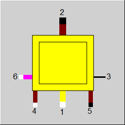 |
Display Option 1 |
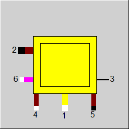 |
Display Option 2 |
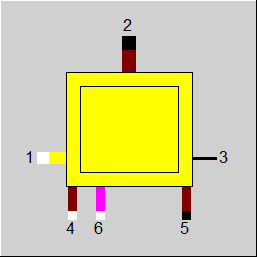 |
Display Option 3 |
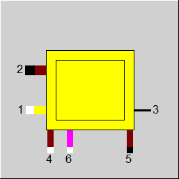 |
Display Option 4 |
 |
Display Option 5 |
Click here >> Component 21 Demo << to load an example.