EBSILON®Professional Online Documentation


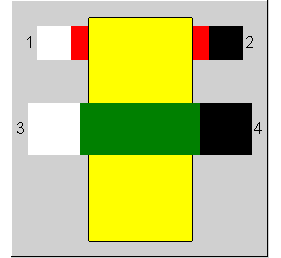
Since the component represents a shaft sealing, it also contains ports for the shaft connections, but the values of which are simply passed through. The equations are valid for all gaseous media. Therefore, the application of this component is not limited to steam
|
Line Connections |
|
|
|
1 |
Leakage Inlet |
|
|
2 |
Leakage Outlet |
|
|
3 |
Shaft Inlet |
|
|
4 |
Shaft Outlet |
|
General User Input Values Physics Used Displays Example
The component "Shaft seal” models steam leakages at the shaft ducts of the steam turbine. In design mode, either geometric data and pressure differences (with calculation of the resulting leakage quantities) or the leakage quantities (with calculation of the resulting seal characteristic) can be specified. In (off-design) simulation mode, the leakage quantities are calculated as a function of the seal characteristic and the current pressure difference as the impellent gradient.
Mass flow reversal can be calculated if Pout > Pin (FDIR=1).
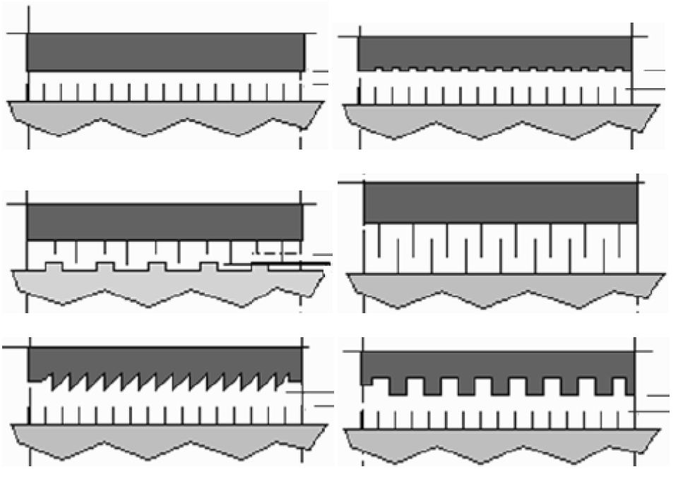
Due to the very high temperatures and the high rotational speed in steam and gas turbines, non-contacting labyrinth seals are still the typical choice for shaft sealing in the power industry.
The following figure shows a few typical configurations for labyrinth seals (Literature 3):
|
FMODE |
Flag for Calculation Mode =0: GLOBAL = 1: Local off-design = -1: Local design |
|
FSPEC |
Flag for Specifications for Design Mode =0: Mass flow (M1N) given =1: Geometry given =2: Mass flow set externally |
|
FDIR |
Flag for Flow Direction =0: No reverse Flow =1: Allow reverse flow |
|
FIDENT |
Flag for Component identification method =0: no identification method =1: Identification of flow |
|
FLAB |
Flag for Leakage Loss Equations =0: Martin's Formulation =1: Egli's Formulation |
|
M1N |
Mass Flow (nominal) |
|
NTEETH |
Number Of Teeth |
|
CFLOW |
Seal Flow Factor |
|
DIAM |
Shaft Diameter |
|
CLEARANCE |
Clearance |
|
PF |
Leakage Factor |
|
CAN |
C*A Value (nominal) |
The identification values marked in blue are reference values for off-design mode. These values are referred to for the actual off-design values used in the equations respectively. If these identification values are stream data, then these values are often taken from attached pipes or calculated values.
Generally, all inputs that are visible are required. But, often default values are provided.
For more information on colour of the input fields and their descriptions see Edit Component\Specification values
For more information on design vs. off-design and nominal values see General\Accept Nominal values
The calculation of the leakage flow is based on the works of Martin (Literature 1) and Egli (Literature 2).
The leakage flow can be defined as follows
 (Equation 1)
The Flow Coefficient is dependent of the seal geometry and has the order of magnitude of 1. Typical values are in the range of 0.4 to 2.

This area is a function of the shaft diameter and the clearance.
see Equation 2.
The Labyrinth Factor is calculated as follows:
 (Equation 2)

 (Martin (Lit.1 )) (Equation 3a)
 (Martin (Lit. 2)) (Equation 3b)
 (Equation 4)

 (Equation 5)
The above mentioned formulas are valid for:
 (Equation 6)
 (Equation 7)
If the pressure ratio is smaller than the critical pressure ratio, the flow remains constant with the value as per the critical pressure ratio.
The critical pressure ratio is derived as follows:
 (Equation 8)
Solving this equation leads to:
 (Equation 9)
It is important to use the one branch of the LambertW() function which has a solution in the interval
The Figure 1 below shows b according to Martin’s formulation (Equation 2, Equ. 3a, Literation. 1)
Fig. 1: Labyrinth Factor according to Equ. 2 using Martin’s Formulation (K=1)
Combining Equation 1 with Equation 2 and replacing
 (Equation 10)
![]()
![]()
Leads to:
 (Equation 11)
For using the component in performance monitoring applications, a Leakage Factor is added, which shall have a value of 1 for design conditions.
 (Equation 12)
The Performance Factor represents the degradation of the sealing relative to the initial state, expressed in terms of the ratio of the leakage flows under identical conditions.
In addition, all geometry data can be simplified to a factor C*A.
 (Equation 13)
 (Equation 14)
In design mode, the user can either specify the geometric dimensions of the labyrinth seal and EBSILON will calculate  and C*A, or the user sets and the program will determine C*A according to Equation 14. The leakage factor is ignored in design mode (PF = 1).
The number of teeth is always an input. If sufficient data are available (several load points), the number of teeth can be estimated from Figure 1, since it significantly influence the shape of the curve. Otherwise, the number of teeth has to be assumed.
In off-design mode, the nominal values for CA and n are fixed, and thus the leakage flow is calculated according to Equation. 14.
(1) Martin, H. M., "Steam Turbines”, The Engineer, London, 1913, p. 1610
(2) A. Egli, "The Leakage of Steam Through Labyrinth Seals” , Transactions American Society of Mechanical Engineers, Paper FSP-57-5, 1935
(3) EPRI Report, ”Replacement Interstage Seals for Steam Turbines”. EPRI, Palo Alto, CA: 2005. 1010214., http://mydocs.epri.com/docs/public/000000000001010214.pdf
(4) Andreas Matthias, ”Das Durchflussverhalten von Labyrinthdichtungen”, Dissertation TU-Wien, 1997, http://publik.tuwien.ac.at/files/pub-mb_5718.pdf
(5) Heinz K. Müller, ”Drosseldichtungen für Gase”, www.fachwissen-dichtungstechnik.de, Kapitel 17 (http://www.fachwissen-dichtungstechnik.de/Kapitelseiten/Kapitel17.html )
(6) Walter Traupel, ”Thermische Turbomaschinen”, Band 1, Kapitel 10, Springer Verlag, 4. Auflage
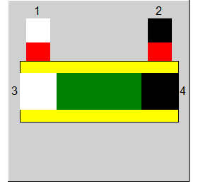
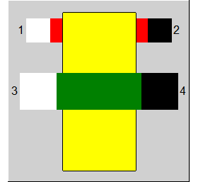 |
Display Option 1 |
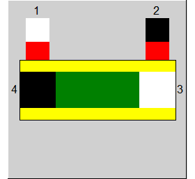
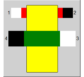 |
Display Option 2 |
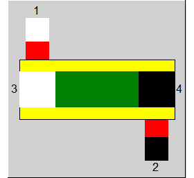
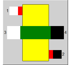 |
Display Option 3 |
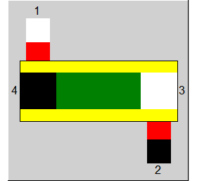
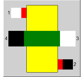 |
Display Option 4 |
 |
Display Option 5 |
 |
Display Option 6 |
 |
Display Option 7 |
 |
Display Option 8 |
Click here >> Component 123 Demo << to load an example.