

|
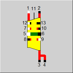
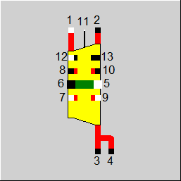
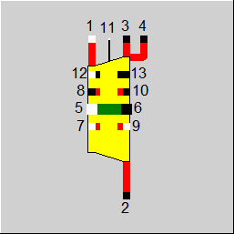
Line connections |
|
|
|
1 |
Steam inlet |
|
|
2 |
Steam outlet |
|
|
3 |
Extraction 1 |
|
|
4 |
Extraction 2 |
|
|
5 |
Shaft inlet |
|
|
6 |
Shaft outlet |
|
|
7 |
HP leakage inlet |
|
|
8 |
HP leakage outlet |
|
|
9 |
LP leakage inlet |
|
|
10 |
LP leakage outlet |
|
|
11 |
Control inlet for performance factor |
|
|
12 |
SCC Grouping Connector in |
|
|
13 |
SCC Grouping Connector out |
|
General Calculation Calculation Flow Efficiency According to SCC Governing Stage Efficiency Turbine Section Internal Efficiency
Moisture Correction Exhaust Losses Mechanical Efficiency Leakage Flows References User Input Values Characteristic Lines Displays ExampleThis component describes a section of a steam turbine (optionally as section between inlet and outlet or in between sections separated by extractions and/or admissions). In case of representing the high-pressure section, the component may also include a governing stage at the inlet.
The authors of the following publications are comprised under the abbreviation SCC:
Spencer, R.C., Cotton K.C. and Cannon, C.N., 1974, ”A Method for Predicting the Performance of Steam Turbine Generators, 16,500 kW and Larger”, ASME Power Division, Paper No. 62- WA-209, USA.
In this paper, the authors developed correlations to the efficiency as a function of five quantities determining the overall loss of the steam turbine based on series of measurements on steam turbines of various configurations and design sizes:
Diagrams and equations were developed for each of these influencing variables allowing to determine the efficiencies of the governing stage and the HP-, IP-, and LP-section of the steam turbine based on few parameters for the design case and the (off-design) simulation case.
For the application in EBSILON, the integration of this methodology is highly useful for the user, because when calculating the steam turbine without available concrete manufacturer data, on the one hand the efficiency in the design case can be estimated very well, and because on the other hand; also when the user defines the design efficiencies; the part-load calculation in off-design mode is based on reliable and consistent data records.
This component contains the correlations of Spencer, Cotton, and Cannon for the governing stage and the HP-, IP-, and LP-sections of a steam turbine as given in Figures 2 to 18 of the publication mentioned above. By selecting the configuration and specifying the inlet and outlet parameters of the selected steam turbine, the user can define the respective correlation for determining the design efficiency. In the off-design calculation, the deviation of the efficiency in relation to the design case is determined according to the figures. A further correction of the efficiency in this component regards the mean valve characteristic line (mean of valve loops correction), which corrects the efficiency assumed in the above-mentioned figures in the case of totally opened valves downward as a result of the restriction effect of the partially closed valves as a function of the relative flow rate.
Besides the equations for the internal efficiency according to Figure 14 of the SCC paper, this component also contains the correlations for the exit loss that can be determined by selecting characteristic geometric values (blade length in the last row of blades, reference diameter, and exit surface) and by characteristic speeds from Figure 16 to 18 of the SCC publication, respectively. In addition, the input of the polytropic efficiency and the calculation of the barrier pressure (exhaust hood choking) are integrated in this component.
Different to Component 6 in which the turbine characteristic is described by defining the isentropic efficiency and one-dimensional correction curves for part-load, this component offers several internal methods for calculating the turbine efficiency under design conditions and at part-load. By defining a few key parameters it is possible; without extensive data requirements; to produce a realistic representation of the turbine characteristics over a wide operating range.
Nevertheless, in case that sufficient data are available (OEM data or measurements), the component also allows to use EBSILON standard inputs and curves for fine-adjustment. The identification mode effectively supports deriving the respective parameters.
The identification modes FIDENT = 1, 2, 3 are used to find the necessary PFETA and PFFLOW in order to match the inlet pressure (PFFLOW) and/or the exit enthalpy (PFETA) respectively. Please note that PFETA is applied to the dry efficiency (i.e. before moisture correction). The flow-bowl-pressure relationship is as follows: flow rate = PFFLOW*f_stodola(bowl-pressure, ...).
The component also works with non-H2O fluids. This deactivates the SCC methods, which are based on regression data from water vapor turbines. Depending on the selected material values, longer calculation times may also occur.
The calculation of the steam turbine has two objectives:
(1) the determination of the flow characteristics which describe the correlation of throughput and inlet pressure, and
(2) the power output which is determined as shaft power by means of an efficiency model.
Besides the internal expansion efficiency, the inlet and outlet structures also affect the apparent (effective, overall) total efficiency, and therefore the turbine is divided into several sub-sections:
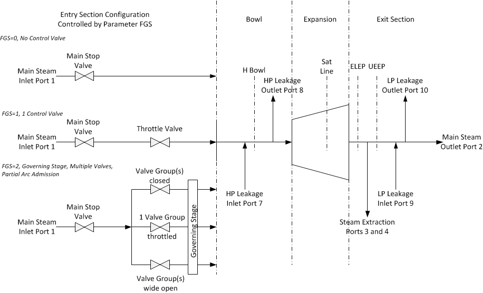
By defining configuration parameters the user selects which sub-sections shall apply to the current usage of the component.
The governing stage is calculated according to W. Traupel (Literature 3) Section 12.2 and is only applicable to power calculations which are not performed according to the method of Spencer, Cotton and Cannon (SCC), i.e. efficiency methods FETAD = 0, 1, 2 or 3 which in the following are also referred to as 'Non-SCC Mode'.
In non-SCC mode, a governing stage is activated with the setting FGS = 5 or 6.
With FGS = 6, one can calculate a govering stage alone, without a following turbine section.
This allows, if necessary, to split the high pressure section into 2 successive components, the first with FGS = 6 modelling the governing stage and the second with FGS = 0 modelling the following part from the bowl to the outlet.
FGS = 5 combines both parts.
FGS = 1: Control valve added. Causes only pressure decoupling at the inlet (like component 14).
FGS = 2: Control valve + control wheel. The number of valves is set via CVSFRAC. CVSFRAC represents the area distribution of the individual valve sections with partial pressurisation:
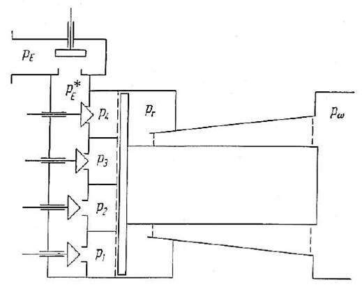
The following equations apply to the governing stage. The bowl pressure pr is solved in the design from GSPR (pressure ratio of the governing stage pi/pr assuming that all valves are fully open in the design) and in the off-design from the cone law of the turbine section (instead of equation 12.2(13)).
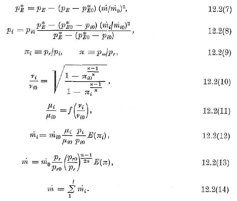
The relative running number is calculated according to 12.2(10) and used in 12.2.(11).
The curve for 12.2(11) (relative suction number) was taken from 12.2.3 and stored as characteristic curve CGSMY. In the lookups, this curve is scaled so that it has the value 1 at the design point, i.e. it passes through (1|1).
The isentropic efficiency of the control wheel is set in the design with GSETAI. In the offdesign, there is the charline CGSETA. This curve is also scaled in the lookups so that it has the value 1 at the design point, i.e. it passes through (1|1).
These equations are solved simultaneously.
In the off design, it must still be determined how many valves are fully open and which one is currently throttled (the rest are closed).
For this purpose the current capacity m_cap is calculated (results from the current pressure ratio over the control wheel with the wheel chamber pressure pr from the cone law).
Now form mfrac = m/m_cap and look up in the charline CVSCAP which valve section you are in.
Since the flow scales with the area, you can determine which valves need to be fully open (VWO) and which is currently throttled.
Since the flow that is throttled has a different autrittsenhalpy, you still have to mix both flows to the wheel chamber condition.
In the wheel chamber, the leakages on the inlet side (via the shaft seal) are added or removed.
Then the whole flows through the actual turbine section.
In design mode, the pressure losses of the main shut-off valve (DPMSV), the fully open control valves (DPCVWO) and the pressure ratio of the control wheel stage (GSPR) must be set. The wheel chamber pressure is calculated as follows: Pb = P1*(1-DPMSV)*(1-DPCVVWO)*GSPR.
In the off-design, a corresponding Stodola relationship applies to GSPR. The calculation of the pressure losses across the valves can be found in the operating simulation (off-design) section of the description of the flow characteristics.
In some SCC modes (FSCC = 0, 1 and 2) there are also control wheel stages, but these are calculated via the calculation rule (Lit. 1). There are separate input parameters for these.
The steam turbine outlet is configured though the parameter FSECT in which configurations with or without accounting for exhaust losses can be selected. This parameter also defines, if moisture removal is included, which will produce different enthalpy values at the extraction ports 3 and 4 compared to the main outlet at port 2. In general, the enthalpy at the ports 3 and 4 are identical.
The flow characteristic (inlet pressure as function of steam flow) is determined according to Stodola's law (lit. (3)). For this purpose, the same formulation is used as already present in EBSILON Professional.
FP1N = 0: The inlet pressure P1 is set via the parameter P1NSET. The component will generate an equation for P1 at port 1.
FP1N = 1: The inlet pressure P1 is defined by external components.
FP1N = 2: The inlet pressure P1 is defined by a kernel expression EP1. The component will generate an equation for P1 at port 1. The standard values include a basic structure of this function.
Taking account of valve losses (DPMSV and DPCVVWO in case of a governing stage) and of the pressure ratio of the governing stage (if defined) the bowl pressure of the turbine is determined based on the inlet pressure P1
The outlet pressure P2 is always defined by external components (e.g. the subsequent condenser).
In off-design, the pressure is calculated from back end to front end by means of off-design correlations.
The off-design bowl pressure determined based on Stodola’s law from the nominal values set in the design run. The same applies, if present, for the governing stage. In this case there is an additional distinction between valve sections in the position valve-wide-open (VWO) and the valve section, in which the control valve is throttled. The calculation is according to Traupel (Literature 3) Section 12.
The capacity and the number of the individual valve sections are defined in Non-SCC mode (FETAD ≤ 3) by means of the char line CVSCAP. In this curve one can find, which sections are fully opened, which sections are throttled and which are closed at the current operating point.
The pressure calculation of the governing stage according to Traupel also includes the char line CGSMY which describes the load-dependent swallowing capacity of the governing stage in off-design. The look-up parameter of this curve is the speed ratio (German ’Laufzahl’) n, and the standard values correspond to the values of Traupel (Literature 3).
The valve pressure drop is determined through the quadratic correlation

In addition, a performance factor can be applied, depending on the setting of the switch FPFFLOW either as a scalar (PFFLOW) or in form of a char line (CPFFLOW). The performance factor only affects the Stodola correlation and does not apply on the valve losses.
For the governing stage exists the char line CGSPFFLOW for adjustments.
The outlet pressure P2 is always determined by external components.
If the calculation of exhaust losses is activated (FSECT = 1, 2, 5 or 6), the choking pressure of the expansion will be determined, which will then be used in the calculation of the resulting shaft power and in the Stodola correlation. The correction Factor CFAEXH allows to adjust the effective area used in the choked flow calculations.
In non-SCC mode (FETAD ≤ 3) the power produced by the governing stage and by the turbine section will be determined separately. The overall efficiency of the turbine section results from the internal expansion efficiency with deduction of the moisture losses and exhaust losses.
As per the procedures of the SCC-modes (FETAD = 4 and or FETAOD < 12), the respective power calculation is identical for both, the design and the off-design calculation.
This component now allows to use the Stodola formula in such a way that the pressures are specified and the steam mass flow is calculated (FSTODOLA=1).
Since the correlations for estimating steam turbine efficiency according to Spencer, Cotton and Cannon (Lit. 1) were derived from experimental investigations on steam turbines larger than 16.5 MW, these correlations are strictly speaking applicable to this power range only. In addition, the correlations for the low pressure section are only valid for inlet pressures larger than 20 psi (1.34 bar), so that the validity of this method cannot be guaranteed for turbine sections with lower inlet pressures (as for instance LP-preheater trains or with steam turbines for districting).
Depending on the selected configuration the SCC formulas include the governing stage as well as the turbine section efficiency with moisture and exhaust losses. The calculation procedure distinguishes various configurations (the entire steam turbine at FSCC = 0, or individual sections at FSCC > 0) for which the overall efficiency is determined based on empirical correlations:
FSCC = 0: Non-reheat, 2-row governing stage, condensing
FSCC = 1: HP Section, 1-row governing stage, non-condensing
FSCC = 2: HP Section, 2-row governing stage, non-condensing
FSCC = 3: IP Section, non-condensing
FSCC = 4: LP Section, condensing
FSCC = 5: LP Section, half-speed, condensing
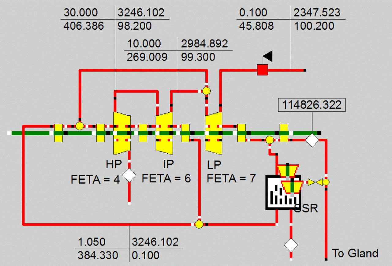
An example of the configuration of a steam turbine model using SCC correlations that also includes the leakage losses newly introduced with Component 122 is shown in Figure 1 below. The individual sections differ according to their respective function in the setting of the parameter FSCC.
The following input parameters are specific to individual SCC modes and will not be used in other calculation modes.
In design mode the isentropic efficiency is determined by the parameter GSETAI.
In off-design, the isentropic efficiency is calculated from the nominal value ETAIGSN in conjunction with the char line CGSETA for which the standard values have been derived from data by Traupel. The look-up parameter of this correction curve is the speed ratio n (see Lit. 3). The char line CGSPFETA allows fine tuning of the governing stage efficiency
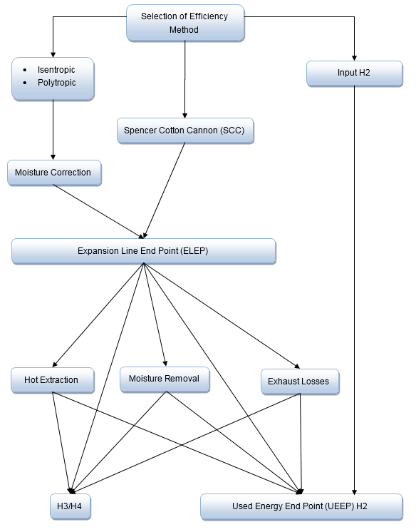
For calculation modes FETAD ≤ 3 (isentropic, polytropic, specification of H2 or shaft power) the parameter Efficiency Definition (FSPEC) defines, if the specified efficiency includes moisture and exhaust losses (FSPEC = 1) or not (FSPEC = 0). In other words: FSPEC defines, if the specified efficiency is related to the actual exit conditions (UEEP = Used Energy End Point, inclusive of moisture and exhaust losses), or to the end point of the expansion line without moisture correction (ELEP = Expansion Line End Point).
Depending on the user settings for FETAD and FSPEC the calculation is performed front to back, or back to front:
The efficiency must be defined by the user in the methods FETAD = 0 or 1. The way in which the efficiency is specified is governed by the parameter FSETA:
The calculation in non-SCC modes (FETAD ≤ 3) is governed by the off-design efficiency method defined with the parameter FETAOD. It is possible to use the nominal values for isentropic or polytropic efficiency with and without correction curves, but also to define the off-design efficiency by means of the kernel expression EETA (see above).
FETAD ≤ 3 in combination with FETAOD = 12 allows to combine non-SCC design run and SCC off-design behaviour. For this purpose an efficiency offset for SCC is calculated during the design run (NDELTASCC) to get the same exit enthalpy when using SCC. Therefore all Off-Design specific SCC settings have already to be set in the design profile.
The moisture correction is applied exclusively to section of the expansion line which crosses the wet steam area. For this purpose, the condensation point of the expansion line has to be determined. The model is based on the assumption that the expansion line progresses along a polytropic line which is defined according to Stodola:

The correction factor is defined as a function of the average moisture content Y which is determined as the arithmetic mean of the moisture content at the inlet and the exit of the section. If Y is higher than the maximum implicitly defined through the minimum steam content at the exit X2MIN, i.e. Y > (1-X2MIN), then a warning will be issued and the calculation of the moisture correction will be performed with this maximum moisture content.
The isentropic efficiency of the expansion line in the wet steam area is multiplied with a correction factor which is determined according to the following options:
In general, the calculation of exhaust losses has to be applied to the last turbine sections only in order to correctly represent the losses related to the fluid flow through the last row of blades at the back-end of the steam turbine. For high pressure and intermediate pressure sections, the expansion line has to be defined without correction (FSECT = 0).
The conditions at the expansion line end point (calculated from exit pressure and internal efficiency) are valid at the section main steam exit at port 2 as well as at the extraction ports 3 and 4.
Exhaust losses are considered in the calculation, if the input parameter Main Steam Exit Enthalpy Calculation (FSECT) is set to 1, 2, 5 or 6. This measure also activates the choking pressure calculation.
For calculating exhaust losses, the exhaust annulus area must be defined. In design mode, this is accomplished by specifying the number of flow ends and either the annulus area per flow end or the superficial steam exit velocity. Based on these inputs, the nominal exhaust annulus area per flow end is determined.
The parameter Exhaust Loss Method (FDHEXHA) defines the way in which the exhaust losses are defined:
In the mode Adjust For Exhaust Losses (FSECT = 1) without moisture correction, the value calculated from the above methods will be directly used.
In the mode Adjust For Exhaust Losses Moisture Corrected (FSECT = 2) the value calculated from the above methods will be interpreted as isentropic loss at dry conditions, so that the effective loss at the expansion end point can be determined as DHEXH = DHEXHA* ETAIDRY*CF(FMOISL).
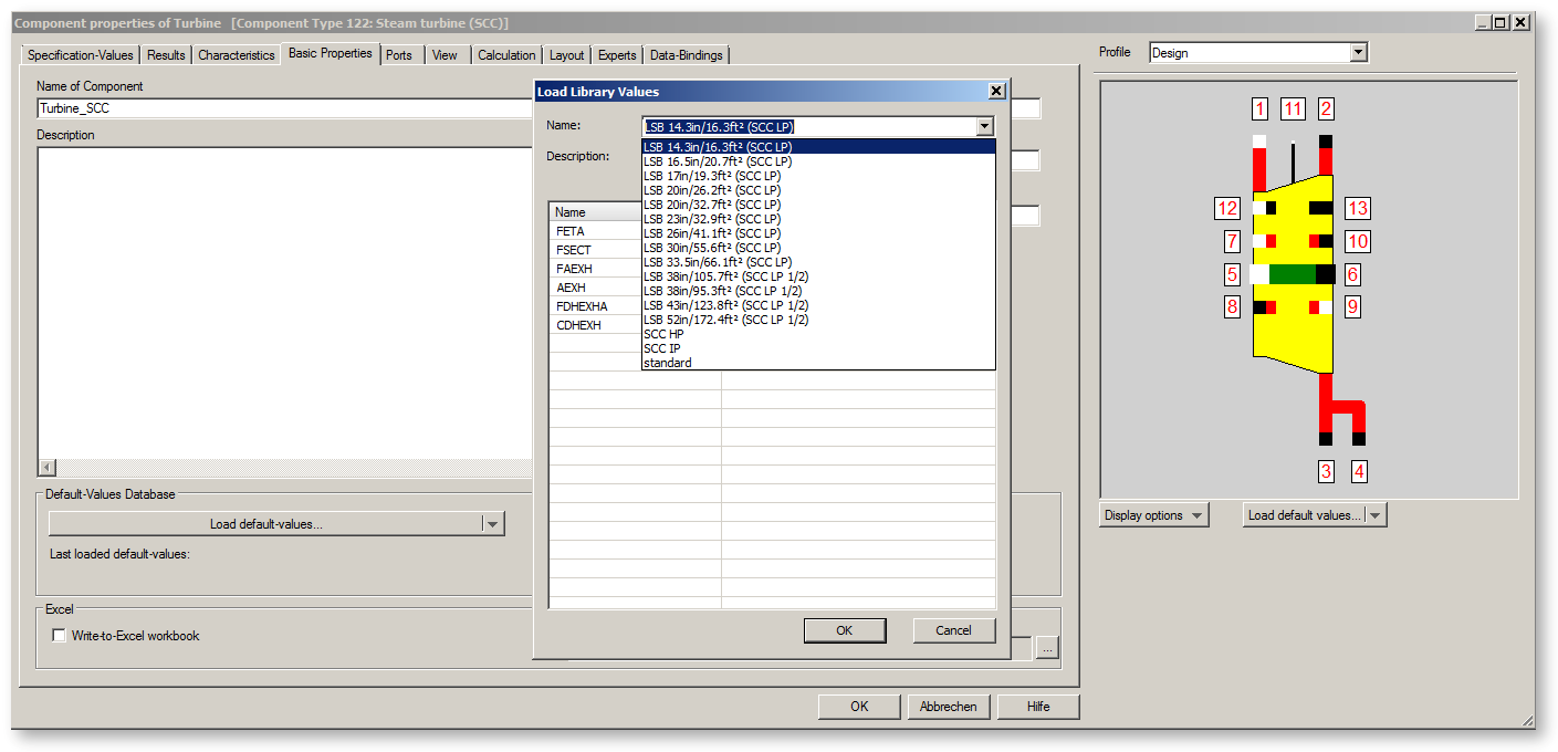
The SCC exhaust loss curves are included in component 122 as sets of Standard Values. You can select the respective curve from the Basic Properties tab with the command 'Load standard values'. From the drop down list of library values you can select the curves ranging from 14.3" to 52" in last stage blade (LSB) length. Selecting a specific set will populate the parameters FETAD, FSCC, FSECT, FAEXH, AEXH, and FDHEXHA as well as the characteristic line CDHEXH with the corresponding values to reflect the performance characteristics defined in the SCC publication.
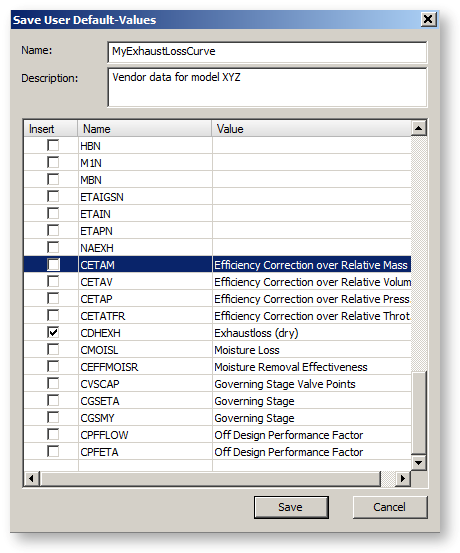
You can add your own current data for exhaust loss characteristics to the standard values by choosing the command 'Save user standard values...'. After saving, the name of the set will be available in the drop-down list of library values.
The enthalpies H3 and H4 differ by a user-defined value of DHEXTR from h_ELEP. The mass flow of the extractions is set from external, and h_UEEP results from the energy balance.
In case of moisture removal mainly liquid water will be extracted from the flow. The liquid flow is determined by the moisture removal effectiveness. The parameter FEFFMOISR determines how it is specified.
In a further step the vapour fraction and the extraction mass flow are determined based on the settings for the parameter FM34:
Finally h_UEEP will be determined from the balances for mass and energy.
The shaft power (SHAFT_POWER) is calculated using the user input for Mechanical Efficiency (ETAMN) and/or Mechanical Losses (QLOSSM) resulting in effective shaft power (DQ65) as follows:
DQ65 = SHAFT_POWER * ETAMN - QLOSSM
The model assumes that all leakage flows are associated with the shaft. Therefore, there can only be one mass flow on the inlet and outlet side respectively, although two ports (in or out) are available on the high pressure and low pressure side, respectively. Even if all leakage ports are connected, only two leakage flows can be > 0.
The leakage ports always determine the pressure and always expect the mass flow to be set from external (e.g. by Component 123 'Shaft Sealing’))
The leakage flows at the inlet come from or enter the bowl, respectively.
Leakage flows exiting at the turbine outlet have the same conditions as the Used Energy End Point (UEEP), i.e. after exhaust losses and/or moisture removal.
Leakage flows entering at the turbine outlet mix with the main steam after expansion and losses (UEEP) and H2 and M2 result according to the respective flow ratio.
Strictly speaking, the estimates for the steam turbine efficiency specified by Spencer/Cotton/Cannon are only valid for complete sections (either high-pressure, intermediate pressure or low-pressure section).
The application to individual discs done in Ebsilon is often outside the range of validity of the SCC formulae. There has been an error message pointing to this fact.
To allow for a correct application of the SCC procedure also when modeling individual discs, it is possible to combine the turbine discs in groups to which the SCC method is then applied in their entirety. To do so, the turbine discs belonging together have to be connected via the logic connections 12 and 13. The required information is then exchanged via these logic lines to carry out the SCC calculation for the entire group.
(1) Spencer R.C., Cotton K.C., Cannon C., "A Method for Predicting the Performance of Steam Turbine Generators. 16.5 MW and Larger.” ASME Paper 62-WA-209, Annual Winter Meeting, New York, N.Y., 1962.
(2) Cotton K.C., "Evaluating and Improving Steam Turbine Performance” , Cotton Fact Inc., 2nd Edition 1998
(3) Walter Traupel, ”Thermische Turbomaschinen”, Band 1/2, Kapitel 10, Springer Verlag, 4. Auflage
|
FMODE |
Flag for using Calculation mode =0: GLOBAL =1: local off-design (i.e. always off-design mode, even when a design calculation has been done globally) =-1: local design |
| Identification and Validation (Off-Design) | |
|
FIDENT |
Flag for using the component identification =0: Off =1: Identify Performance Factor Efficiency =2: Identify Performance Factor Bowl Pressure =3: Identify (both)Performance Factors for Efficiency and Bowl Pressure =11: Identify Performance Factor Efficiency (Feedback on Port 11 H) =12: Identify Performance Factor Bowl Pressure (Feedback on Port 11 M) =13: Identify (both)Performance Factors for Efficiency and Bowl Pressure (Feedback on Port 11 M,H) Then a 2nd run is performed where the pressure is calculated as above (using the cone law+PF) and the efficiency like at mode 'Set H2', giving the present internal efficiency: i.e. which inner efficiency is needed to reach the desired exit enthalpy. Now the following is calculated: So the task is as follows: |
|
FETAN |
Flag for Off-Design : Nominal dry efficiency (for Validation) =0: Off (use internal Nominal Efficiency ETAIN) =1: On (Read from logic line H on port 11) |
| Pressure and Flow Settings | |
|
FP1N |
Flag for the inlet pressure handling =0: P1N=P1NSET (Off Design: by Stodola equation) =1: P1-given from outside =2: P1=EP1 (equation / script) |
|
P1NSET |
Inlet pressure (nominal) |
|
FP1OD |
Flag for off-design inlet pressure calculation =0: Use Stodola Pressure-Flow Relatio =1: P1-given from outside =2: P1=EP1 (equation / script) =3: Use Stodola Pressure-Flow Relation, extended for Small Number of Stages =4: Calculate PB from AEN (PB=critical_flux(PB,HB)*AEN) |
|
EP1 |
Expression for Desired Inlet Pressure function evalexpr:REAL; |
|
FPRCRIT |
Flag for the critical pressure ratio calculation =0: Estimate from number of stages in axial section =1: Use value PRCRIT =2: Use matrix-lookup MXPRCRIT =3: Use expression EPRCRIT |
|
NSTAGES |
Number of stages in axial section (for evaluation of PRCRIT) |
|
PRCRIT |
Critical pressure ratio |
|
EPRCRIT |
Expression for critical pressure ratio |
|
FSTODOLA |
Flag for Off-Design Stodola Mode =0: Calculate Pressure from Flow =1: Calculate Flow from Pressure |
|
NFENDS |
Number of flow ends |
|
FSTODTOL |
Flag for Off-Design Stodola Violation Tolerance =0: Always Set Error Message =1: Tolerate difference up to STODTOL |
|
STODTOL |
Pressure Difference Tolerance (Required inlet pressure greater than supplied inlet pressure) |
| Turbine Entry Section | |
|
DPMSV |
Main Stop Valve - Pressure Drop (Design) |
|
FGS |
Flag for the configuration of the entry section =0: no control valve, no governing stage =5: governing stage using CVSCAP valve schedule =1: one control valve, no governing stage =6: governing stage only using CVSCAP valve schedule (no axial section) =2: deprecated: multiple valves (CVSCAP mass floPw based) with governing stage =3: deprecated: multiple valves (CVSCAP area based) with governing stage =4: deprecated: Off Design: Valves Wide open with governing stage |
|
FGSOD |
Flag for the mode of operation of the entry section in off-design =0: Standard behaviour =1: Valves wide open (VWO) =2: Set valve point with ODVPNT =3: Use Logic Port 11 P-value as Valve Point (FIDENT=0 only) |
|
FGSODNY |
Speed ratio definition =0: Relative pressure ratio =1: Relative available energy SQRT(AEN/AE) |
|
FGSNOZZLETYPE |
Governing stage nozzle type =0: Converging Nozzle =1: Converging-Diverging Nozzle (de Laval Type) |
|
DPCVVWO |
Relative pressure drop of control valve - valves wide open (non-SCC) |
|
GSPR |
Governing Stage Pressure Ratio (Design, non-SCC) |
|
GSETAI |
Governing Stage Isentropic Efficiency |
|
ODVPNT |
Governing Stage Off-Design Valve Point (Fraction from 0 to 1 for closed to wide open) |
| Turbine Main Section Efficiency | |
|
FETAD |
Flag Design Efficiency Method =-1: Bypass ST =0: Isentropic efficiency (FSPEC is relevant) =1: Polytropic efficiency (FSPEC is relevant) =2: Exhaust Enthalpy =3: Shaft Power externally set =4: SCC method, specified in FSCC |
|
FSCC |
Flag SCC Method =-1: Bypass ST =0: Non Reheat Steam Turbine With 2-Row Governing Stage, Exhaust Losses specified in FSECT (NVALVES is relevant) =1: HP Section with 1-Row Governing Stage, no Exhaust Losses (NVALVES, GSPD are relevant) =2: HP Section with 2-Row Governing Stage, no Exhaust Losses (NVALVES, GSPD are relevant) =3: IP Section, non condensing, no Exhaust Losses =4: SCC; LP Section, condensing, Exhaust Losses specified in FSECT =5: SCC; LP Section, Half Speed incl., Condensing, Exhaust Losses specified in FSECT |
|
FSPEC |
Flag for Efficiency Definition =0: Expansion Line End Point (ELEP) =1: Used Energy End Point, (UEEP), (with moisture and exhaust losses) |
|
FETAOD |
Flag for OFF-Design Method for Efficiency (Dry) =0: ETAIDRY = ETAIN =1: ETAPDRY = ETAPN =2: ETAIDRY = Use Kernel Expression (EETA) =3: ETAPDRY = Use Kernel Expression (EETA) =4: ETAIDRY = ETAIN * mass flow characteristic line CETAM (M1/M1N) =5: ETAIDRY = ETAIN * flow rate characteristic line CETAV (VM1/VM1N) =6: ETAIDRY = ETAIN * pressure characteristic line CETAP [(P1/P2) / (P1N/P2N)] =7: ETAIDRY = ETAIN * CETATFR (TFR/TFRN) =8: ETAPDRY = ETAPN * mass flow characteristic line CETAM (M1/M1N) =9: ETAPDRY = ETAPN * flow rate characteristic line CETAV (VM1/VM1N) =10: ETAPDRY = ETAPN * pressure characteristic line CETAP [(P1/P2) / (P1N/P2N)] =11: ETAPDRY = ETAPN * CETATFR (TFR/TFRN) =12: SCC method, specified in FSCC. All related SCC settings (FSCC, etc.) must already be set correctly during Design run. SCC-Grouping is not supported. |
|
FSETA |
Flag for Efficiency Input Definition (if FETA = 0 or 1) =0: use value ETAN =1: use kernel expression EETA |
|
ETAN |
Input Value for Efficiency |
|
EETA |
Kernel Expression for Efficiency function evalexpr:REAL; var val:real; begin internals := keGetInternals(); { for i := 0 to n-1 do if (n > 0) then M1M1N:=internals[0].value; // TODO: calculate eta and set val to it // println( "Return Value: ", val ); |
|
FETA |
Deprecated:Flag Specification Efficiency Method =-2: Use FETAD (Default) =-1: Bypass ST =0: Isentropic efficiency (FSPEC is relevant) =1: Polytropic efficiency (FSPEC is relevant) =2: Exhaust Enthalpy =9: Shaft Power =3: SCC; Non Reheat Steam Turbine With 2-Row Governing Stage, Exhaust Losses specified in FSECT (NVALVES is relevant) =12: SCC; Non Reheat Steam Turbine With 2-Row Governing Stage, Non-SCC Exhaust Losses specified in FSECT =4: SCC; HP Section with 1-Row Governing Stage, without Exhaust Losses (NVALVES, GSPD are relevant) =5: SCC; HP Section with 2-Row Governing Stage, without Exhaust Losses (NVALVES, GSPD are relevant) =6: SCC; IP Section, non condensing =7: SCC; LP Section, condensing, Exhaust Losses specified in FSECT =10: SCC; LP Section, condensing, Non-SCC Exhaust Losses specified in FSECT =8: SCC; LP Section, Half Speed, Condensing, Exhaust Losses specified in FSECT =11: SCC; LP Section, Half Speed, Condensing, Non-SCC Exhaust Losses specified in FSECT |
| SCC related Settings | |
|
SCCTF |
Technology Factor to account for technical advances (value of 1.01 represents efficiency improvement by 1%, e.g. 90% -> 90.9%) |
|
NVALVES |
Number of control valves (for FETA = 3,4 and 5 only) |
|
GSPD |
Governing Stage Pitch Diameter (for FETA = 3,4 and 5 only); only researched in the range of 30 -46 Inch |
|
FMOISL |
Flag for Moisture Loss Method =0: Spencer Cotton Cannon (SCC) =1: Baumann-Factor =2: Miller-Schofield (Cannon, Traupel) =3: Characteristic line CMOISL =4: Usage of Kernel Expression EMOISL |
|
BFMOISL |
Baumann-factor |
|
EMOISL |
Moisture loss Kernel Expression (eta wet/ eta dry) |
| Turbine Exit Section | |
|
FSECT |
Flag to define the calculation of the main steam exit enthalpy (H2) = 0: Use Expansion Line End Point (H2, H3 and H4 = HELEP) = 1: Adjust for Exhaust Loss (H2, H3 and H4 = HELEP; DHEXH = DHEXHA) = 2: Adjust for Exhaust Loss Moisture Corrected [H2, H3, H4 = HUEEP; DHEXH = DHEXHA * ETAIDRY * FMOISL(xELEP)] = 3: Hot Extraction: No exhaust loss (H2< H3, H4) = 4: Moisture Removal, No exhaust Loss (H2> H3, H4) = 5: Adjust for Exhaust Loss Moisture Corrected as in SCC [H2, H3, H4 = HUEEP; DHEXH = DHEXHA * 0.87 * (1-xELEP) * (1-0.65*xELEP)] = 6: Adjust for Exhaust Loss Moisture Corrected (H2, H3, H4 = HUEEP; DHEXH = DHEXHA * (1-xELEP)) = 7: Adjust for Exhaust Loss with enhanced moisture correction FMOISL |
| Exhaust Loss | |
|
FAEXH |
Flag to define the exhaust annulus sizing mode =0: Velocity =1: Area |
|
CFAEXH |
Correction factor for flow area for last stage choking (S ABlade = CFAEXH*AEXH) |
|
AEXH |
Exhaust Annulus Area per Flow End |
|
VEXH |
Exhaust Annulus Velocity in each Flow End |
|
FDHEXHA |
Flag to define the exhaust loss method =0: Set Value =1: Char Line CDHEXH =2: Use of Kernel Expression EDHEXHA =3: Use Volumetric Char Line CDHEXHVOL |
|
DHEXHA |
Exhaust Loss |
|
EDHEXHA |
Exhaust Loss Kernel Expression |
|
DHEXTR |
Enthalpy difference extraction ELEP |
| Moisture Handling | |
|
FEFFMOISR |
Flag to define the moisture removal mode =0: Set value for effectiveness (EFFMOISR) =1: char line for effectiveness =2: expression for effectiveness |
|
EFFMOISR |
Input value for moisture removal effectiveness (if FEFFMOISR = 0) |
|
EEFFMOISR |
Kernel expression for moisture removal effectiveness (if FEFFMOISR = 2) |
|
FM34 |
Flag to define the extraction flow mode =0: internally set by X34 =1: externally set |
|
X34 |
Extraction flow steam fraction |
| Mechanical Efficiency | |
|
ETAMN |
Mechanical Efficiency (nominal) |
|
QLOSSM |
Mechanical Loss (constant fraction) |
| Off-Design Performance Factor | |
|
FPFETA |
Flag for off-design performance factor efficiency =0: use PFETA =1: use char line CPFETA =2: use logic port 11 H-value for input (FIDENT<10 only) =3: use expression EPFETA =4: use all available for input |
|
PFETA |
Performance factor efficiency (applied to dry efficiency) |
|
EPFETA |
Expression for performance factor efficiency (applied to dry efficiency) |
|
FPFFLOW |
Flag off-design performance factor on flow =0: use PFFLOW =1: use char line CPFFLOW =2: Use logic point 11 M-value for input (FIDENT<10 only) =3: use expression EPFFLOW =4: use all available for input |
|
PFFLOW |
Performance factor flow (flow rate = PFFLOW*f_stodola(pressure)) |
|
EPFFLOW |
Expression for performance factor flow (flow rate = PFFLOW*f_stodola(pressure)) |
| Limits | |
|
T1MAX |
Maximum inlet temperature |
|
X2MIN |
Warning limit minimum for exit vapour fraction |
| Nominal Values from Design Run | |
|
P1N |
Nominal inlet pressure |
|
PBN |
Nominal bowl pressure |
|
P2N |
Nominal outlet pressure |
|
H1N |
Nominal inlet enthalpy |
|
HBN |
Nominal bowl enthalpy |
|
M1N |
Nominal inlet mass flow (VWO throttle flow) |
|
MBN |
Nominal bowl mass flow |
|
ETAIGSN |
Nominal governing stage isentropic efficiency |
|
ETAIN |
Nominal isentropic efficiency (ELEP) |
|
ETAPN |
Nominal polytropic efficiency (ELEP) |
|
NAEXH |
Nominal exhaust annulus flow area per flow end |
|
NDELTASCC |
Nominal SCC Delta Efficiency (used in FETAOD=12). FETAOD and all related SCC settings (FSCC, etc.) must already be set correctly during Design run. SCC-Grouping is not supported. |
|
NAEN |
Nominal effective Nnozzle area |
The parameters marked in blue are reference quantities for the off-design mode. The actual off-design values refer to these quantities in the equations used.
Generally, all inputs that are visible are required. But, often default values are provided.
For more information on colour of the input fields and their descriptions see Edit Component\Specification values
For more information on design vs. off-design and nominal values see General\Accept Nominal values
Efficiency Correction
Exhaust Loss (dry)
Moisture Loss
Moisture Removal Effectiveness
Governing Stage
Governing Stage Valve Points
Off-design Performance Factor
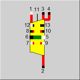
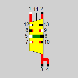
The ports and displays are fundamentally identical to those of component 6. Additional inlet and outlet ports are provided for consideration of leakage streams.
 |
Display Option 1 |
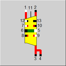 |
Display Option 2 |
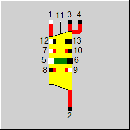 |
Display Option 3 |
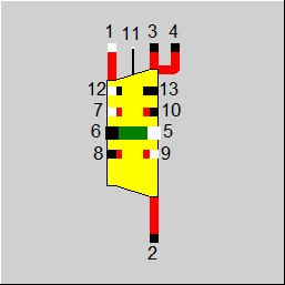 |
Display Option 4 |
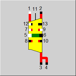 |
Display Option 5 |
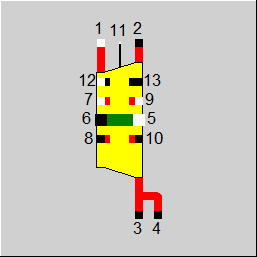 |
Display Option 6 |
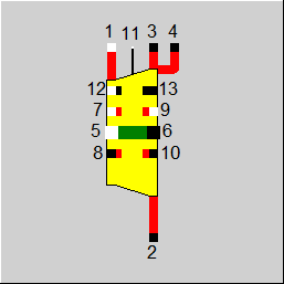 |
Display Option 7 |
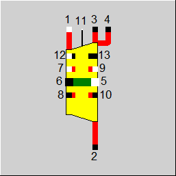 |
Display Option 8 |
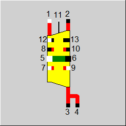 |
Display Option 9 |
 |
Display Option 10 |
 |
Display Option 11 |
 |
Display Option 12 |
 |
Display Option 13 |
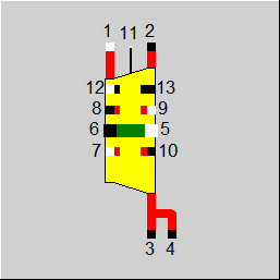 |
Display Option 14 |
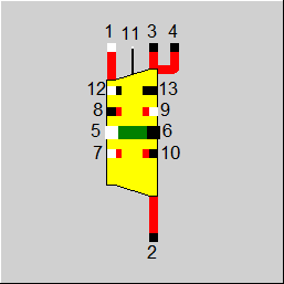 |
Display Option 15 |
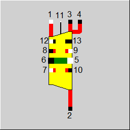 |
Display Option 16 |
Click here >> Component 122 Demo << to load an example.