EBSILON®Professional Online Documentation


|
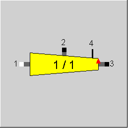
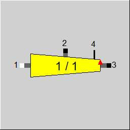
Line connections |
|
|
|
1 |
Fluid inlet |
|
|
2 |
Representative branch |
|
|
3 |
Remaining outlet |
|
|
4 |
Logic connection to collecting header |
|
General User Input Values Physics Used Diagrams Displays Example
The component 114 "distributing header" is used to split a mass flow connected to point 1 ("Fluid inlet") into two flows. While the simple splitter components in EBSILON®Professional only care for the mass balance, component 114 offers a heat and momentum balance, too. The component is intended to model a header that equally distributes a fluid stream on a number of branches. Such a configuration can be found in solar thermal power plants with parabolic trough technology where a large number of collector loops are connected to one header. Only one "representative branch" is modelled via connection point 2. It is possible to define that not all of the mass flow is distributed over the branches but a remaining portion leaves the component at connection point 3 ("Remaining outflow").
Connection point 2 describes one representative branching point. Although equal distribution of mass on all branches is assumed, the branching points along the header may have different enthalpies and pressures due to heat and pressure loss effects. The user has to choose which thermodynamic properties (pressure and temperature) he considers as representative for his application. Several options are available.
The user has to specify how many branching points are located along the header. It is assumed that the number of branching points is equal to the number of sections between these branching points. This means that the first branching point is located downstream of the first header section. The last branching point is located downstream of the last header section and thus at the end of the header.
Due to some differences in the functionality of the two models, a distributing header (114) and a collecting header (115) are available.
|
NBRANCH |
Number of sections and thus branching points in the header |
|
IBRANCH |
Position of representative branching point in the header (red triangle in the graphics)
|
|
NLOOPS |
Number of loops connected to each branching point (Integer) |
|
IDP |
Position of node for pressure loss calculation (1<=IDP<=NBRANCH) |
|
FSPECM |
Definition of mass flow split method Expression =0: Remaining outflow M3 given from external =1: Split ratio M3 to M1 prescribed by M3M1 =2: M3 calculated from M2 and M3M1 |
|
M3M1 |
Ratio of M3 to M1 (used if FSPECM=1) |
|
FREPH |
Method for calculation of enthalpy at branch Expression =0: Local value at IBRANCH =1: Temperature average over all NBRANCH branches =2: Enthalpy average over all NBRANCH branches |
|
FREPP |
Method for calculation of pressure at branch Expression =0: Local value at IBRANCH =1: Maximum pressure drop over header (equal to DP13) =2: Automatic search for maximum overall pressure drop over both headers |
|
LSECT |
Length of header section between two branching points |
|
FDADAPT |
Assumption for diameter profile along the header (used if FDPN=1/2) Expression =0: constant diameter given by DDESIG =1: diameter profile to obtain constant velocity given by VDESIG |
|
DDESIG |
Header inner diameter (constant along header, used if FDPN=1/2 and FDADAPT=0) |
|
VDESIG |
Header design velocity (constant along the header, used if FDPN=1/2 and FDADAPT=1) |
|
FMODE |
Flag for calculation mode (design / off-design) Expression =0: Global =1: local off-design (i.e. always off-design mode, even when a design calculation has been done globally) = -1: local design |
|
FDPN |
Method for calculation of nominal pressure loss Expression =0: Given by parameter DP12N =1: Calculation single phase =2: Calculation two phase |
|
DP1RN |
Nominal pressure loss between inflow 1 and node IDP |
|
DP13N |
Nominal pressure loss between inflow 1 and outflow 3 |
|
FDPPL |
Method for calculation of part-load pressure loss Expression =0: Depending on mass flow =1: Depending on mass and volume flow =2: Constant at nominal value (calculated according to FDP12N) =4: Calculation single phase =5: Calculation two phase |
|
ZETAARM |
Singular pressure loss coefficient at branch |
|
KS |
Equivalent sand roughness of inner pipe surface (used for pressure loss calculation) |
|
FQLOSS |
Method for calculation of heat losses to surrounding Expression =0: Specific heat loss prescribed by QSLOSS =1: Specific temperature drop prescribed by TSLOSS =2: Specific enthalpy drop prescribed by HSLOSS =3: Heat loss calculated by heat loss model |
|
QSLOSS |
Length-specific heat loss (constant along the whole header, used if FQLOSS=0) |
|
TSLOSS |
Length-specific temperature drop (constant along the whole header, used if FQLOSS=1) |
|
HSLOSS |
Length-specific enthalpy drop (constant along the whole header, used if FQLOSS=2) |
|
RATISOL |
Insulation material thickness (ratio of outer to inner diameter if insulation material, used if FQLOSS=3) |
|
LAMISOL |
Heat conductivity of insulation material (used if FQLOSS=3) |
|
CORQLOS |
Factor to tune the heat loss obtained from the heat loss model (used if FQLOSS=3) |
|
FSTAMB |
Definition of ambient temperature (required for model based heat losses) Expression =0: Given by parameter TAMB =1: Taken from superior SUN component with index ISUN |
|
TAMB |
Ambient temperature (used if FQLOSS=3 and FSTAMB=0) |
|
ISUN |
Index of reference solar data component |
|
M1N |
Mass flow inlet (nominal) |
|
M3N |
Mass flow remaining outlet (nominal) |
|
P1N |
Pressure inlet (nominal) |
|
H1N |
Enthalpy inlet (nominal) |
|
VR12N |
Specific volume at reference point 1-2 (nominal) |
|
VR13N |
Specific volume at reference point 1-3 (nominal) |
|
TAMBN |
Ambient temperature (nominal) |
The parameters marked in blue are reference quantities for the off-design mode. The actual off-design values refer to these quantities in the equations used.
Generally, all inputs that are visible are required. But, often default values are provided.
For more information on colour of the input fields and their descriptions see Edit Component\Specification values
For more information on design vs. off-design and nominal values see General\Accept Nominal values
|
QLOSS12 |
Heat loss between fluid inlet and representative branch |
|
QLOSS13 |
Heat loss of the complete header |
|
QLOSSA |
Mean length-specific heat loss |
|
DT12 |
Temperature drop between fluid inlet and representative branch |
|
DT13 |
Temperature drop between fluid inlet and remaining outlet flow |
|
DP12 |
Pressure drop between fluid inlet and representative branch |
|
DP13 |
Pressure drop over the complete header |
|
DPZETA |
Additional pressure drop at representative branch |
|
DPSA |
Mean length-specific pressure drop |
|
DMAX |
Maximum diameter |
|
DMIN |
Minimum diameter |
|
RTAMB |
Ambient temperature used for calculation |
|
RNBRANCH |
Number of branches used for calculation |
|
RIBRANCH |
Representative branch used for calculation |
|
RNLOOPS |
Number of loops per branch used for calculation |
|
RLSECT |
Length of one section used for calculation |
|
RISUN |
Index used for calculation |
The mass flow M1 entering the component is split into NBRANCH*NLOOPS equal mass flows M2 into the branches and a remaining mass flow M3 that leaves the header at the end. The ratio of M3 to M1 has to be prescribed by parameter M3M1 or M3 is given externally on the line.
M2 = (M1-M3) / (NBRANCH*NLOOPS).
The parameter NBRANCH describes the number of sections along the header. After each section, a fraction of the mass flow is taken out into the branch. This fraction can be distributed equally on NLOOPS loops at the branching point. The motivation for this option is the fact that, in parabolic trough power plants, two collector loops (north and south loop) are normally connected to one branching point. By specifying NLOOPS=2 this behaviour can easily be represented.
Thermodynamic properties at the representative branch
EBSILON®Professional calculates the specific enthalpy and pressure at each of the NBRANCH branching points along the header. For the simulation one representative branching point is used. This representative does not necessarily match one physical branching point of the header but has to be chosen based on the physics of the components connected to it.
If a line of solar collectors is connected it would be reasonable to have the representative branch at an average temperature since the heat losses in the solar collector line depend on the temperature difference to the ambient air. The user has three options to select the specific enthalpy set at the representative branch:
The option FREPH=0 can be used if the minimum (IBRANCH=NBRANCH) or maximum (IBRANCH=1) temperatures are of interest.
In the same way the pressure level at the representative branching point can be chosen. There are three options to define the pressure at the representative branch:
In the third option, EBSILON®Professional looks at the system of distributing and collecting header and identifies the path of maximum pressure drop. For this option it is required to link these two components by a logic line. When this option is active the representative branch gets the pressure of the branching point identified by EBSILON®Professional . Further details to this method are explained in the component 115 help.
The incoming fluid stream M1 is distributed on the remaining outflow M3 and the branches M2. In case no heat losses to the surrounding occur the specific enthalpy at outlets 2 and 3 is the same as at the inlet 1. This is the case if the specific losses of heat QSLOSS, temperature TSLOSS or enthalpy HSLOSS a set to 0.
Heat losses in the sections of the header can be considered by prescribing non-zero values for these parameters. The user has the choice between definition of a length-specific heat loss (FQLOSS=0), temperature drop (FQLOSS=1) or enthalpy drop (FQLOSS=2). The value defined by the user is used to calculate the specific enthalpy at the end of each section. This calculation is done for all sections in series beginning with the first section after the inflow. The inlet conditions of the downstream sections are given by the outlet conditions of the corresponding upstream section. Note that the specific heat loss, temperature drop or enthalpy drop is constant along the whole length. Due to the varying mass flow from section to section the temperature profile along the header is only linear if a constant temperature drop is chosen. Applying a constant specific heat loss will result in a non-linear temperature profile.
As a fourth option, a model based calculation of the heat losses is provided. The effective heat loss in each section is calculated from the difference between fluid and ambient temperature based on a radial heat conduction in the insulating material. The nominal heat loss in a section i of the header is calculated according to the formula
Q_0(i)=2*pi*LSECT*LAMISOL*1 / ln(RATISO) * CORQLOS * ( T_0(i) - Tamb_0) ,
where LAMISOL is the ration of outer to inner insulation material diameter (constant along the header) and CORQLOS is a parameter to tune the model result. T_0(i) is the fluid temperature (at the center of each section) and Tamb_0 the ambient temperature.
In part-load operation it is assumed that heat losses are linear in the temperature difference between fluid and ambient air. Thus, losses are calculated based on the nominal values by means of
Q(i) = Q_0(i) * ( T(i) - Tamb) / ( T_0(i) - Tamb_0) .
Although the ambient temperature in the design point is only required if the model based calculation (FQLOSS=3) is selected the ambient temperature is stored as a reference point for the part-load heat losses.
Due to varying mass flow rates and diameter (optional) along the header the length-specific pressure drop along the header will not be constant. In order to avoid detailed pressure drop calculations section by section it is assumed that the specific pressure drop can be approximated by a second-order polynomial. Integration of this polynomial along the header yields the pressure difference between two distinct locations, namely DP12 as the pressure drop between inlet 1 and representative branch 2 IBRANCH and DP13 as the overall pressure drop between inlet 1 and outlet 3. Three nodes are required to determine the coefficients of the polynomial. The first node is located at the inlet 1, the second at position IDP and the third one at outlet 3. The user can decide weather to
An additional singular pressure loss at the branches can be specified by parameter ZETAARM.
The pressure loss model described in component 113 is used here to calculate specific pressure losses (Pa/m) at the three nodes. This requires an assumption on the header diameter at these positions. Two options are available:
In the second option the diameter is calculated based on the nominal mass flow and density in the respective sections. Note that due to the calculation method a continuous profile of the diameter is assumed to approximate the section-wise constant profile in a real system.
At each branching point an additional pressure drop for the branch can be imposed by defining a pressure drop coefficient ZETAARM. According to VDI heat atlas the pressure drop is imposed between the main flow upstream of the branching point and the branch. A pressure drop for the main flow (upstream to downstream of the branching point) is not considered since it is normally much smaller. The pressure drop DPZETA is calculated as
DPZETA = ZETAARM * RHO * VEL**2 / 2.
The velocity is the one upstream of the branching point. If a constant diameter in the header is chosen (FDADAPT=0) the velocity depends on the section and thus on the parameter IBRANCH. For FDADAPT=0 (constant velocity) the velocity and thus DPZETA are independent of IBRANCH.
The user has the following options for the calculation of the part-load pressure loss:
 |
Display Option 1 |
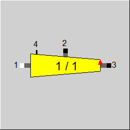 |
Display Option 2 |
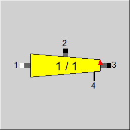 |
Display Option 3 |
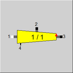 |
Display Option 4 |
Click here >> Component 114 Demo << to load an example.