EBSILON®Professional Online Documentation


|
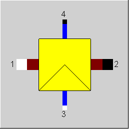
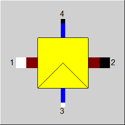
Line connections |
|
|
|
1 |
Inlet |
|
|
2 |
Outlet |
|
|
3 |
Water injection |
|
|
4 |
Water outlet |
|
General User Input Values Result Values Physics Used Displays Example
The component 97 serves for modeling a saturizer, in which a gaseous carrier fluid (air, flue gas, fuel gas or raw gas), water as liquid or steam is fed.
Depending upon the pressure and the temperature of the carrier fluid, a certain quantity can be absorbed by the carrier current in gaseous state (saturation). While in case of a simple saturizer (component 53) the water quantity is determined by the fact that exactly only so much water is fed, which the carrier fluid can absorb, in case of component 97 it is possible to specify any quantity of water. Hence, the component also possesses an additional exit for draining away excess water. How much water is to be drained out via this exit, can be determined in two ways:
This can lead to an super saturation in the carrier fluid (in this case the water is fed in the carrier fluid in liquid form) or to an under saturation (in this case, the relative humidity in the carrier fluid, indicated as the result value PHI2, is less than 1)
While injecting water in liquid form, heat is needed for evaporation. In case of a simple saturizer, this always leads to a cooling down of the carrier fluid. In case of component 97 it is also possible to extract the heat of evaporation from the water current. This can be done in any of the following three ways
If T4 and/or M4 is given externally, the calculated values are entered to specifications DT43 and/or MAM3 during the transfer of the reference values.
This component does not distinguish between design and off-design.
Table Differences for Injections (see Release 12, Section 1.3.5)
In the case of the component “Water injection“ (38) as well as both saturizer components (53, 97) it is necessary to transfer the injected water that is calculated in the injection line
according to the water/steam table (usually IAPWS-IF97) into the flue gas, where the calculation is carried out with pressure-independent FDBR polynomials. There are different
options regarding the point where this table transfer is carried out; these lead to slightly different results in each case. These differences are due to the fact that the treatment of the
steam as ideal gas represents an approximation that becomes inaccurate at high pressures and lower temperatures in particular. In concrete terms this means that the modeling of
the injection will become the more realistic the later the table transfer takes place.
It is also possible to perform this panel transition one step later.
Here the previous results can be reproduced with FTABC=0.
with
FTABC=1 It is now possible to carry out this table transfer another step later
|
FSPECT |
Type of specification of sub cooling: Like in Parent Profile (Sub Profile option only) Expression = 1: sub cooling calculated with specified by the user input value DT43=-1: T4 entered from outside |
|
DT43 |
Sub Cooling of the water coming out: |
|
FSPECM |
Type of specification of water separation Like in Parent Profile (Sub Profile option only) Expression = 1: Water separation is calculated with the user input value MAM3=-1:M4 entered from outside |
|
MAM3 |
Percentage of water absorbed from the fed water: The percentage MAM3 of the water fed in line 3 is fed to |
|
FTABC |
Material table conversion point Like in Parent Profile (Sub Profile option only) Expression = 0: For all the water at outlet temperature and total pressure (old mode) = 1: For gaseous fraction of water after expansion to partial pressure
|
Generally, all inputs that are visible are required. But, often default values are provided.
For more information on colour of the input fields and their descriptions see Edit Component\Specification values
For more information on design vs. off-design and nominal values see General\Accept Nominal values
|
PHI2 |
Saturation at the gas-outlet (relative moisture): |
|
All Cases |
||
|
|
If MAM3 is given: M4 - (1-MAM3) * M3 = 0
M2+M4-M1-M3 = 0
P2-P1 = 0
P4-P2 = 0
If DT43 is given: T3 = f (P3, H3) T4 = T3 - DT43 H4 = f (P4, T4) DH43 = H4 - H3 H4 - H3 = DH43
M1*H1+M3*H3-M2*H2-M4*H4 = 0
|
|
 |
Display Option 1 |
Click here >> Component 97 Demo << to load an example.