
EBSILON®Professional Online Documentation


|
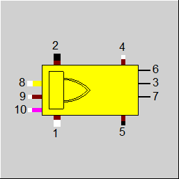
Line connections |
|
|
|
1 |
Flue gas inlet |
|
|
2 |
Flue gas outlet |
|
|
3 |
Wall heat flow outlet Connection to attached main heating surface, component 89 |
|
|
4 |
Ash inlet |
|
|
5 |
Ash extraction |
|
|
6 |
Heat flow by radiation up Radiation flow to upstream heating surface component 89 |
|
|
7 |
Heat flow by radiation down Radiation flow to downstream heating surface component 89 |
|
|
8 |
Air inlet |
|
|
9 |
Fuel inlet |
|
|
10 |
Additional fuel inlet (if available) |
|
General User Input Values Characteristic Lines Physics Used Displays Example
Module 90 together with component 89 (steam generator, main heating surface) or component 91 (steam generator, auxiliary heating surface) allows for the geometry-based representation of combustion and heat transfer in the combustion chamber of a steam generator.
Module 90 represent a flue gas zone with combustion, which can contain a main heating surface (component 89). For that purpose PIN 3 of the combustion zone (component 90) shall be connected with PIN 3 of a main heating surface (component 89). In addition, the radiation flow from the flue gas volume in the zone to the upstream and / or downstream heating surface component 89 can be taken into account. For this purpose, PIN 7 can be connected with PIN 5 of the main heating surface (component 89) in the upstream flue gas zone and correspondingly PIN 6 with PIN 4 of component 89 in the downstream zone.
Unlike component 21 (combustion chamber), the outlet temperature can not be given using nominal value and characteristic curve, but is calculated from the heat input and the heat exchange with the main heating surface.
Concerning the calculation of heat transfer and radiation flow, component 90 behaves as module 88 (steam generator, flue gas zone), which does not take combustion into account.
The NOX and CO concentration, respectively at the outlet can be specified via a kernel expression. This is controlled via the flags FNOCON and FCOCON:
The flag FCON controls whether the concentration is given as a volume fraction or as a standardized mass fraction (mg/Nm³).
MODEL
It takes into account
The component calculates
H1 or H2, M1 or M2, if in each case one of them is given.
H4 or H5, M4 or M5, if in each case one of them is given.
H8 and H9 (or/and H10) must be given as well as M8 and M9 (or/and M10) or M8 or M9 (or/and M10) and the air ratio ALAM
P2 = P1 - DP12 as well as P1=P5=P8=P9 (or/and P10) and P4=P2, i.e. one of the pressures P1, P2, P4, P5, P8, P9 (or/and P10) must be given.
Pressure Drop for “Boiler: reaction zone” DP12
The pressure drop in the furnace usually refers to the pressure difference between inlet and outlet of the flue gas. In the lowest stage, however, no flue gas is present at the inlet yet.
But the pressure had to be specified there in order to receive the correct outlet pressure.
Note : This has been changed: if no line is connected at the flue gas inlet (Pin 1), the pressure at the outlet (Pin 2) is calculated in comparison to the air inlet (Pin 8).
CALCULATION FUNDAMENTALS
At first, a combustion calculation is done for determining the flue gas composition and the adiabatic combustion temperature TAD (result value).
For this purpose, the fuel fractions of fuel (9) (or/and 10), ash (4) and flue gas (1) are cumulated. The burnt part of the total fuel ETABN (combustion efficiency) completely reacts with the total air from air inlet (8) and flue gas inlet (1). The unburned fuel (1-ETABN) is distributed to ash outlet (5) and flue gas outlet (2) according to the parameter UBASH (portion of unburnt fuel in ash).
A partial combustion with CO formation can be mapped at the outlet by specifying the CO concentration. However, the specification of an air ratio < 1 is currently not implemented, because it will result in component errors.
The ash fractions from fuel feed (9) (or/and 10) and ash feed (4) are cumulated and distributed to the flue gas outlet and the ash extraction according to the parameter RFLAN (fly-ash portion in the total ash). The ash extraction is done with at least one of the temperatures defined by the parameter TASHE.
There are several variation possibilities for specifying the unburnt fuel:
The composition of the unburnt fuel can be selected either the same as the fuel composition or as that of pure carbon.
The quantity of the unburnt fuel can be specified as follows:
The flag FTYPUB basically defines, whether
1. ETABN and UBASH or
2. UBSL and UBFL
are specified.
However, further possibilities result from the increase of the parameter RFLAN:
1. Specification: ETABN / UBASH / RFLAN -Calculated: UBSL / UBFL (as case 1 above)
2. Specification: UBSL / UBFL / RFLAN - Calculated: UBASH / ETABN (as case 2 above)
3. Specification: UBSL / UBFL / ETABN - Calculated: UBASH / RFLAN
4. Specification: UBSL / UBFL / UBASH - Calculated: ETABN / RFLAN
In other words: If one specifies UBSL and UBFL, there is no need to specify RFLAN; Instead of that, ETABN or UBASH can also be specified independently, however,
then RFLAN should not be specified, because it results.
The gasification of ash ASG can be taken into account. According to DIN EN 12952 5% is to be assumed for burner and stoker-firing and 0% for fluidized-bed firing.
The calorific value of the unburnt fuel can be specified. DIN EN 12952 recommends here 33000 kJ/kg for hard coal and 27200 kJ/kg for lignite. By default, however, EBSILON®Professional calculates the value from the elemental analysis.
The cp-value of the ash can be specified. This is done through a correction factor, with which the calculated cp-value is multiplied. For ash in waste gas and in the slag different correction values can be specified. The DIN EN 12952 recommends
cpSlag = 1,0 kJ/kgK in case of dry firing,
1,26 kJ/kgK in case of slag-tap firing
cpFlydust = 0,84 kJ/kgK (between 25 and 200 °C)
This corresponds to correction factors of 1.02 or 1.28 for cpSlag and 0.86 for cpFlydust respectively (at 200 °C)
The balancing of the energy flows assigned to these material flows results in the heat content of the flows at the flue gas outlet and ash outlet as well as the adiabatic
combustion temperature TAD.
The heat transfer to the main heating surface (component 89), which is attached to the combustion zone is calculated in component 89 and copied to component 90 using the logic lines. In addition, module 90 calculates the radiation flow to the upstream or the downstream surfaces, which may be attached to it according to
QR_6 = PHI6_I*CS*EBS3_I*(1-EBS6_I)*LAMBDA*(TRADH6**4-TRADL6**4)*BEW3
QR_7 = PHI7_I*CS*EBS3_I*(1-EBS7_I)*LAMBDA*(TRADH7**4-TRADL7**4)*BEW3
Form factors PHI, emissivities EBS, efficiency factors are evaluated in the attached modules, and transferred by logic lines. The radiation temperature of the emitting zone is a weighted average of the adiabatic combustion temperature TAD and the flue gas outlet temperature T2
TRADH6=TRADH7= ALPHA_T *TAD + (1-ALPHA_T)*T2+273.15
The weight factor ALPHA_T is set as specification value under EXTRAS->MODEL OPTIONS->SIMULATION (Calculation).
The radiation flows are always positive i.e. there is no radiation flow into the flue gas originating from heating surfaces with a higher radiation temperature than the flue gas. The radiation temperature of the main heating surfaces is the average wall temperature:
TRADL6 = TWAND6
TRADL7 = TWAND7
Similar to component 88, the contributions from the gas radiation and the solid particles radiation, possibly containing ash and soot particles, are taken into account for calculating the emissivities, as well as a contribution of the unburnt fuel particles for solid fuels. For this purpose, a portion PERCOKE of the solid fuel with a particle distribution described by the specification values CSCOKE, DIACOKE and DISTCOKE is equally spread out over the volume of the zone and is calculated with the same formula as an emissivity fraction for the ash loading.
Radiation losses can be specified either through the relative loss (DQLR) or from the C-factor and the nominal useful heat is calculated (DQ = C * QNMAX ^0.7, QNMAX in MW).
COMPONENT IDENTIFICATION
There is no identification mode for component 90.
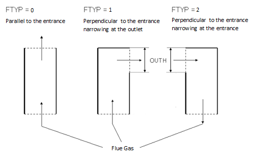
GEOMETRIC DISPLAY OF FLUE GAS ZONES
The arrangement of inlet and outlet area of the flue gas zone essentially influences the calculation of the form factor PHI. To represent the different types of steam generator design with or without direction changes in the flue gas path, the specifications values OUTH and FTYP can be used. Their use is illustrated in the diagram given below:
Note about the air ratio:
The flag FALAM is used to switch whether the air ratio is determined by the specification value ALAMN or by both mass flows on the fuel and the air inlet. In each case, the air ratio is displayed as result value ALAM. This value is defined ALAM in EBSILON®Professionalon the air flow that is inserted via the air pipe. If there is some air on the fuel line (this is the case when the mill is included in the model, e.g.), the result value ALAM does not match the value of the air ratio that is expected by the O2 concentration in the flue gas.
For this reason, there is the result value ALAMT (total air ratio). This value is determined by the O2 concentration and therefore independent from the pipe where the air supplied.
Note about the unburnt fuel:
The specification value ETABN (Combustion efficiency, nominal) always refers to solid or liquid fuels. If one connects gas or crude gas to connection 9 (or/and 10), this is then burnt completely. ETABN is then used only for the solid unburnt fractions, which could be available from a previous burner stage via the slag (4) - or the flue gas (1)-inlet (for instance, when one operates the previous stage with coal).
Note - cp correction factors:
The treatment of the cp correction factors has been harmonized for Components 21 and 90. As with Component 90, Component 21 also allows to specify a correction factor CPSL
for the ash in the slag and a correction factor CPFL for the ash in the exhaust gas (fly ash). The cp value calculated by Ebsilon according to the FDBR formula is multiplied by
this factor.
The option to specify the cp correction factor at the fuel consumption and have it transferred to the slag line only existed for Component 21. This is also possible for Component 90
as well, by leaving the value CPSL empty. Analogously, in the case of an empty CPFL the correction factor is transferred from the air line to the exhaust gas line.
With the specification value ASHSPL, Component 90 also allows to apportion the ash coming from above (Pin 4) among the exhaust gas outlet (Pin 2) and the slag outlet (Pin 5).
If the specification value ASHSPL=0, the ash coming from above will always be forwarded to the slag outlet in its entirety.
The NOX and CO concentration, respectively (CO only in the case of components 21 and 90) at the outlet can be specified via a kernel expression. This is controlled via the
flags FNOCON and FCOCON, respectively:
As before, the flag FCON controls whether the concentration is given as a volume fraction (mol/mol) or as a standardized mass fraction (mg/Nm³).
By adding lime into the combustion chamber it is possible to bond the SO2 emerging during the combustion directly as CaSO4. This process can be represented in Ebsilon as well.
The following chemical reactions are considered here:
Calcination:
• Ca(OH)2 à CaO+H2O
• CaCO3 à CaO+CO2
• MgCO3 à MgO+CO2
Bonding of sulfur:
• CaO + SO2 + 0.5 O2 à CaSO4
As these reactions do not take place completely as a rule, the reaction rates are to be specified by the user. This is done by means of the two specification values CALCR
and DESN as well as four kernel expressions ERCAOH2, ERCACO3, ERMGCO3, and ERSO2.
The flag FDES is used to control which values are used:
The solids remaining after the reaction are distributed on the waste gas and slag outlets according to the specifications, like all incombustible solids.
Mg and Ca are metals that are not usually burned. As, however, the new Component Gibbs Reactor treats these elements in balance, they have been included in the list
of available substances as well.
In the Ebsilon components that carry out a combustion, however, these elements are always burned completely. In the exhaust gas and in the slag, there will not be any unburnt Mg or Ca. The specification values in Component 21 and 90 concerning combustion efficiency and distribution of unburnt matters apply (as before) to the elements C, H, O, N, S, Cl only. When specifying unburned matter in Components 21 and 90, this still only refers to the elements C, H, O, N, S and Cl; unburned Mg and Ca do not occur in the exhaust gas.
The combustion products MgO and CaO are divided in the components 21 and 90 according to the default value RFLAN on slag pipe and exhaust pipe, just like all the other non-combustible solids.
Another fuel inlet (Pin 10) has been added to this component to enable an operation with two different fuels (like e.g. oil and gas).
A calculation of the chemical equilibrium based on the NASA code used in the Gibbs reactor (Component 134) can be carried out instead of a combustion calculation. The new flag FOP is used to switch over:
As in Component 21, the possibility to carry out a calculation of the equilibrium instead of a combustion calculation has been created in Component 90 too.
The operation is analogous to Component 21
When specifying a combustion efficiency ETABN < 1, the corresponding fraction of the fuel (C fraction at FUB=1, (C,H,O,N,S,Cl) at FUB=0) is already branched off before the equilibrium is calculated, i.e. it is no longer included in the calculation of the equilibrium. As in the equilibrium, however, possibly not everything is burned either, the combustion efficiency may in total become smaller than the specification.
However, Component 90 features more pins that are treated as follows:
• Exhaust gas inlet from the predecessor stage (Pin 1): the exhaust gas entering here is treated and included in the calculation of the equilibrium just like the combustion air (Pin 8).
• Slag inlet from the predecessor stage (Pin 4): the slag entering here is not included in the equilibrium but leaves the component unchanged; in doing so, it is distributed to Pin 2 (exhaust gas outlet) and Pin 5 (slag outlet) according to specification value ASHSPL.
For the calculation of the flame temperature TF relevant for the radiation exchange, there are two theoretical limit values – the adiabatic combustion temperature Tad and the flue gas outlet temperature Tout.
The flame temperature relevant for the radiation fluxes Q6 and Q7 was calculated with a weighting factor Alpha_T from the model settings (model settings => simulation => calculation).
TF= Alpha_T*Tad+(1- Alpha_T)*Tout , 0<=Alpha_T<=1
For the radiation flow Q3, by contrast, the arithmetic mean value from Tad and Tout was used at all times, which corresponds to an Alpha_T value of 0.5.
In component 90 there are three new specification values – FTRAD, ALPHAT, and ETRAD – that are used for controlling the calculation of the flame temperature TF. It is possible to specify a local value ALPHAT for the component, which is either used only for the radiation flow Q3 or for all radiation flows (Q3 and Q6, Q7). Alternatively, the flame temperature can also be calculated for all radiation flows as geometrical mean value of the Tad and Tout or it can be calculated by the user by means of a Kernel expression ETRAD.
The flame temperature is displayed as result value TRAD.
As Component 21 before, Component 90 allows to make the following settings with the flag FC for the parameter used for calculating the radiation losses:
However, FC is only active if FLOSS has been set to 1 (“Calculation from C and QNMAX “).
|
FCALC |
In the Release 7.00 there is a change in the combustion calculation, which in certain cases leads to slightly different results. For reasons of compatibility, it is possible to continue calculating with the old mode. There are the following changes in the new mode:
Like in Parent Profile (Sub profile option only) Expression =1: Fuel and air strictly separated (old mode, before 2001) =2: Both fuel inlets, mixing with air possible (new mode, after 2016) |
|
FOP |
Operation mode Like in Parent Profile (Sub profile option only) Expression =0: Combustion |
|
FALAM |
Flag for using the given air ratio ALAMN Expression =0: Calculate air flow by using ALAM =1: Set M8 und M9 (or/and M10), calculate ALAM |
|
ALAMN |
Air ratio (air / air stoichiometric) (nom.) See Lambda definitions If FALAM=0, M8/M9 (or/and M10) = ALAMN*DLMIN, where DLMIN is the specific air requirement according to the fuel analysis of the fuel which is fed on line 8 (and not according to the analysis of the total fuel under consideration of the fuel portions on line 1 and 4). M8 and M9 (or/and M10) is set, ALAM is calculated. Irrelevant, if FALAM = 1. |
|
TASHE |
Slag temperature |
|
ASHSPL |
Dispersed ash from pin 4 to exhaust gas |
|
FTRAD |
Calculation of radiation temperature |
|
ALPHAT |
Parameter Alpha_T for radiation temperature |
|
ETRAD |
Function for radiation temperature |
|
DP12N |
Pressure loss 12 in design mode. If the design mode is set, the prescribed value is used. If off-design is set, pressure will be corrected with mass flow and specific volume. |
|
FMODE |
Flag for calculation mode design/off-design Like in Parent Profile (Sub profile option only) Expression =0: GLOBAL |
|
ETABN |
Combustion efficiency (nominal) |
|
ZW |
Width of the flue gas zone ZW and ZD are the dimensions of the cuboid-shaped flue gas zone perpendicular to the flow direction of the flue gas |
|
ZD |
Depth of the flue gas zone ZW and ZD are the dimensions of the cuboid-shaped flue gas zone perpendicular to the flow direction of the flue gas |
|
ZH |
Height of the flue gas zone ZW and ZD are the dimensions of the cuboid-shaped flue gas zone perpendicular to the flow direction of the flue gas |
|
OUTH |
Height of the flue gas outlet, ignored, if FTYP = parallel to inlet. |
|
FTYP |
Arrangement of the flue gas outlet cross-section Like in Parent Profile (Sub profile option only) Expression =0: Parallel to inlet
|
|
FCON |
Flag for specifying the type of specification of NOx- and CO-concentration Expression =1: Molar ratio (relative to reference O2 concentration) =2: Normalized mass ratio at reference O2 concentration The difference between FCON=1 and FCON=2 is the fact that for FCON=2 you have to specify some kind of "density" for the pollutant fraction, i.e. mass of pollutant per volume of flue gas (therefore the dimension mg/Nm³). If you divide this density by the density of the pure pollutant, you get the corresponding volume fraction. In the implementation, the case FCON=2 is traced back to FCON=1, using a constant density of 1.2494 kg/m³ for CO and 2.05204 kg/m³ for NOx (independent of NOSPL). |
|
FCOCON |
Flag for specifying the calculation of the CO-concentration Expression =-1: No CO calculation (FOP=0) or CO calculation according to equilibrium (FOP=1) =0: By specification value COCON =1: By function ECOCON |
|
COCON |
CO-concentration in the exhaust gas (wet molar fraction at reference oxygen concentration), (defined under Extras-> Model Options->Simulation->Calculation). Hint: To reproduce the value COCON in the exhaust gas pipe, you have to change the reference oxygen concentration in the model settings to the mole fraction of oxygen in the exhaust gas pipe and change the properties of the value cross to display mole fraction. As this calculation is performed iteratively, the value is reached only approximately. |
|
ECOCON |
Function for concentration of CO in exhaust gas function evalexpr:REAL; |
|
FNOCON |
Flag for specifying the calculation of the NOx-concentration Expression =-1: No NOx calculation (FOP=0) or Nox calculation according to equilibrium (FOP=1) =0: By specification value NOCON =1: By function ENOCON |
|
NOCON |
NOx concentration in the exhaust gas (wet molar fraction at reference oxygen concentration), (defined under Extras-> Model Options->Simulation->Calculation). From NOCON and NOSPL, the NO and NO2 concentration in the exhaust gas is calculated at actual O2 concentration. Hint: To reproduce the value NOCON in the exhaust gas pipe, you have to change the reference oxygen concentration in the model settings to the mole fraction of oxygen in the exhaust gas pipe and change the properties of the value cross to display mole fraction. NOCON will be the sum of XNO and XNO2. As this calculation is performed iteratively, the value is reached only approximately. |
|
ENOCON |
Function for concentration of NOx in exhaust gas function evalexpr:REAL; |
|
NOSPL |
NO-split of the NOx (NO/(NO+NO2) molar fraction) |
|
RFLAN |
Percentage of unburnable solids going to flue gas outlet (pin 2) |
|
FDES |
Option for desulphurization Expression 0: Not active |
|
CALCR |
Calcination rate |
|
DESN |
Desulphurization efficiency |
|
ERCAOH2 |
Conversion rate for Ca(OH)2-> CaO + H2O function evalexpr:REAL; |
|
ERCACO3 |
Conversion rate for CaCO3-> CaO + CO2 function evalexpr:REAL; |
|
ERMGCO3 |
Conversion rate for MgCO3-> MgO + CO2 function evalexpr:REAL; |
|
ERSO2 |
Conversion rate for SO2 in CaO + SO2 +0.5 O2 -> CaSO4 function evalexpr:REAL; |
|
FTYPUB |
Flag for the type of specification of the quantity of the unburnt fuel (relevant only for solid fuels) Expression =0: Specification of ETABN, UBASH and RFLAN =1: Specification of UBSL, UBFL and RFLAN =2: Specification of UBSL, UBFL and ETABN =3: Specification of UBSL, UBFL and UBASH |
|
FUB |
Flag for setting the composition of the unburnt fuel Expression =0: same as the fuel composition |
|
FUBSL |
Flag for using UBSL: Specification of the unburnt fuel in the slag Expression =0: as fraction of the total slag =1: as fraction of the fuel (combustible at the fuel inlet, given by the elemental analysis without ash, lime, water and gas) |
|
UBSL |
Percentage of unburnt fuel in slag, depending upon FUBSL |
|
FUBFL |
Flag for using UBFL: Specification of the unburnt fuel in exhaust gas Expression =0: as percentage in the fly ash (fraction of ash, coke and unburnt fuel at the flue gas outlet) =1: as percentage in the fuel (combustible at the fuel inlet, given by the elemental analysis without ash, lime, water and gas) |
|
UBFL |
Percentage of unburnt fuel in slag, dependent on FUBFL |
|
UBASH |
defines the distribution of unburnt fuel to the outlets ash extraction (pin 5) Like in Parent Profile (Sub profile option only) Expression UBASH = Part of the unburnt fuel that leaves the component through the ash extraction pipe (5) 1-UBASH = Part of the unburnt fuel that leaves the component through the flue gas pipe (2) For UBASH=0, all unburnt fuel is in the flue gas (pln 2), for UBASH=1, all unburnt fuel is in the ash extraction (pin 5). |
|
ASG |
Percentage of gaseous ash in complete ash (solid and gaseous) at the flue gas outlet |
|
FLOSS |
Flag for specifying the radiation losses Expression =0: Specification through the relative heat loss DQLR =1: Calculation from C and QNMAX (QL = C * QNMAX^0.7 ) |
|
DQLR |
Relative heat loss For FCALC=1 (old mode) relative to Q3 for FCALC=2 (new mode) relative to M9*(H9 + NCV9) and/or M10*(H10 + NCV10) |
|
FC |
Specification of the factor C for radiation losses This parameter is interpreted alternatively as flag or as numeric value. Expression =0: Use specification value C =1: Use EN12952 value for oil and gas boilers (C=0.0113) |
|
C |
Loss factor for radiation losses according to EN12952
|
|
QNMAX |
Maximum useful heat (for calculating the heat loss as per FLOSS) |
|
NCVUB |
Calorific value of the unburnt |
|
CPSL |
Correction factor for the specific heat capacity of slag. The cp-value of the ash determined from the material tables is multiplied with this factor. |
|
CPFL |
Correction factor for the specific heat capacity of flying ash. The cp-value of the ash determined from the material tables is multiplied with this factor. |
|
CSCOKE |
Relative cross-section of the coke for absorption, typically 0.85 The parameters CSASH, DIAASH and DISTASH configure the calculation of the fraction of the solid particle radiation of the fuel in the total emission of the flue gas. |
|
DIACOKE |
Average particle diameter of the coke particles, typical value 6*10**-5 m The parameters CSASH, DIAASH and DISTASH configure the calculation of the fraction of the solid particle radiation of the fuel in the total emission of the flue gas. |
|
DISTCOKE |
Parameter of the Rosin-Rammler distribution of the coke particles, typical value 1.5 The parameters CSASH, DIAASH and DISTASH configure the calculation of the fraction of the solid particle radiation of the fuel in the total emission of the flue gas. |
|
PERCCOKE |
Fraction of the supplied fuel, which effectively contributes to the radiation. PERCCOKE of the supplied fuel is uniformly spread over the volume of the combustion zone. The resulting average coke content is used to calculate the contribution of the radiation of the coke particles to the flue gas emission. |
|
BRUM |
deprecated, use ETABN |
|
M2N |
Outlet flue gas mass flow (nominal) |
|
V2N |
Specific volume at outlet flue gas (nominal) |
|
QN |
Heat transferred from flue gas (nominal i.e. in the design state) |
Degree of desulfurization; the percentage 1-DESN of sulfur in the fuel will be converted to SO2
The identification value marked in blue is the reference value for the off-design mode. The actual off-design values refer to the values used in the equations.
Generally, all inputs that are visible are required. But, often default values are provided.
For more information on colour of the input fields and their descriptions see Edit Component\Specification values
For more information on design vs. off-design and nominal values see General\Accept Nominal values
No characteristic lines are used.
MXRSO2 - is used for the degree of desulfurization
|
Design (Simulation flag: GLOBAL = Design and FMODE = Design) |
||
|
|
P2 = P1-DP12N P8=P1 P9=P1 P10= P1 P5=P1 P4=P2 |
|
|
Off-design (Simulation flag: GLOBAL = Off-design or FMODE = Off-design) |
||
|
|
DP12 = DP12N * V2/V2N * (M2/M2N)**2 P2 = P1 - DP12 P8=P1 P9=P1 P10= P1 P5=P1 P4=P2 |
|
|
All cases
|
||
|
|
M1-M2+M4-M5+M8+M9+M10= 0 (1) ALAM = ALAMN Total fuel = Sum of all fuel fractions in lines 9, 10, 1 and 4 Total air = Sum of all air fractions in lines 1 and 8 Elementary combustion calculation with analysis of total fuel and total air (3) Addition of the fraction 1-UBASH of the unburnt fuel to the flow 2 (flue gas outlet) Total ash 5 = (1-RFLAN)*ash fraction in flow 9 (or/and 10)+ flow 4 + UBASH*unburnt fuel (2) Calculation of the adiabatic combustion temperature TAD from the energy balance of the flows 8, 9, 10, 1, 2, 4, 5 (i.e. without the heat exchange with the walls and radiation) Calculation of the heat values of the flows 2, 4 Losses VERL = QNEN*QVERL TRADL6 = TWAND6 TRADL7 = TWAND7 VERL = DQLR*QVERL Regula Falsi: (Outlet temperature)
TRADH6 = ALPHA_T*TAD+(1.0-ALPHA_T)*T2+273.15 TRADH7 = ALPHA_T*TAD+(1.0-ALPHA_T)*T2+273.15 LAMBDA=0.85 (empirical adjust factor) QR_6 = PHI6_I*CS*EBS3_I*(1-EBS6_I)*LAMBDA*(TRADH6**4-TRADL6**4)*BEW3 QR_7 = PHI7_I*CS*EBS3_I*(1-EBS7_I)*LAMBDA*(TRADH7**4-TRADL7**4)*BEW3
QSUMRG= Q3+QR_6+QR_7+VERL
H2 = H1 - QSUMRG/M2
END Fix point iteration 1
-M2*H2+M1*H1+M8*H8+M9*H9+M10*H10+M4*H4-M5*H5
H5 = f (TASHE) (7) H6 = QR_6 (8) H7 = QR_7 (9)
|
|
|
|
|
|
 |
Display Option 1 |
Click here >> Component_90 Demo << to load an example.