EBSILON®Professional Online Documentation


|
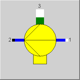
Line connections |
|
|
|
1 |
Water inlet |
|
|
2 |
Water outlet |
|
|
3 |
Required shaft power |
|
General User Input Values Characteristic Lines Physics Used Displays Example
The pressure after the pump can be defined like in component 8 (simple pump). In most cases, this is defined by the flow system, for instance, at the condensate pump of the deaerator and at the feed pump of the boiler. If necessary, the pressure can also be defined with component 33 (start value).
Alternatively, the pressure can be defined within this component (83) using characteristic lines.
There is a rotary speed characteristic for the efficiency too. This characteristic serves only for calculating the isentropic degree of efficiency and has no effect on the handling of pressure and speed. Depending upon the setting of the flag FSPEC the speed is given either as specification value or else is calculated from the pressures. This speed is then used as a parameter for the efficiency characteristics.
In the mode ”power specification” the efficiency characteristic is not used. In this case the speed is determined from the pressure difference (both the pressures must be specified in this case) and the isentropic efficiency is calculated based on the specified power. The efficiency characteristic is not needed for this.
While designing the component it must be noted that the point on the characteristic line representing the design characteristic must run through the point (1, 1). Otherwise, one gets different results when switching over from Design to Off-design.
Component 83 can be used for liquid water, salt water, universal fluids, user-defined fluids, 2-phase liquid fluids, oil streams and thermal oil streams.
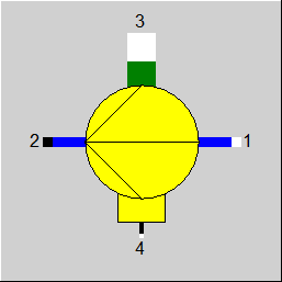
External Specification of the Speed
The rotational speed can also be specified via a logic line (Pin 4). The specification is expected as a mass flow, which can be achieved by a measuring point of the type
“speed” (FTYP=16).
The specification of the rotational speed via the logic line is activated by the flag FSPEC=2. The calculation operation is the same as for FSPEC=1, but instead of the specification
value REVG, the value of the enthalpy of the line is used. When the logic line has been connected, in modes FSPEC=0 and FSPEC=-1 the calculated value for the rotational speed
is written onto this line as enthalpy.
Owing to the extensions for shafts and electric streams it is also possible to specify the rotational speed via the connected mechanical shaft.
The setting FSPEC=3 is used for this.
Implementing a load-independent mechanical loss (QLOSSM) (see Release-Notes for Release 12)
The sequence in which the proportional and the constant fraction are considered depends on the direction of the flow of energy.
If both a mechanical efficiency ETAMN and a constant loss QLOSSM are specified, the two are combined as follows:
Q_gross =( Q_net + QLOSSM) / ETAMN
The result value QLOSS comprises the entire (load-independent and load-dependent) loss
QLOSS = Q_gross – Q_net
The result value ETAM contains both fractions (as in the case of component 6), as ETAM is defined by
ETAM = Q_net / Q_gross
If a QLOSSM > 0 is specified, ETAM thus no longer equals ETAMN but is accordingly smaller (by QLOSSM/heat supply).
Note : For this component there was no result value ETAM up to Release 11; instead, the specification value called ETAMN in other components was called ETAM here. So
Component 83 has specification value ETAMN and result value ETAM as well. When opening a model created with Release 11 or older, the value previously at ETAM is automatically transferred to ETAMN.
Only when using it in EbsScript or EbsOpen it might be wise to check manually.
Relative characteristic field
In the case of the pump (variable speed, Component 83), there is an absolute characteristic field (set of characteristic lines CDPM1_1 to CDPM1_5) for the delivery head (e.g. in meters) had to be entered over the absolute volume flow (e.g. in m³/s). That meant that when using this component, the characteristic field had to be individually adjusted in each case.
Alternatively there is as of Release 11 a relative characteristic field (set of characteristic lines CRDPM1_1 to CRDPM1_5) where quantities related to the nominal value are recorded, i.e. the delivery head (DH/DHN) related to the nominal value DHN over the volume flow (VM1/VM1N) related to the nominal value VM1N. The parameter (the rotation speed) of the set of characteristic lines, however, still has to be specified as absolute.
As the nominal values are adjusted by Ebsilon in the design calculation, the component can be used in the same way in each model, and changes may be made only if so required if deviations occur in off-design behaviour. The flag FDPCHR is used to set whether the absolute or the relative characteristic field is to be used.
A special feature of this component is that here the characteristic line is used in the design case, too, in order to prevent an inconsistent design as it may occur e.g. in the case of the compressor with characteristics (Component 94) if in the design case a flap position is selected for which the corresponding curve of the characteristic field does not go through (1,1).
This means that
• for FSPEC<=0 (P2 specification) the rotation speed is also determined in the design case, i.e. it cannot be specified.
• for FSPEC=1 (specification of rotation speed) the outlet pressure has to be specified in the design case anyway.
The current delivery head is then determined from this, and the nominal value for the delivery head is determined from the corresponding characteristic line (according to the rotation speed).
It does not have to be identical with the current delivery head.
Usually in Ebsilon there is a linear interpolation between the characteristic lines of the set for parameter values lying in between. In the case of this component, however, this contradicts the physical reality, as the delivery head increases quadratically with the rotation speed. For this reason a flag FDPINTP has been implemented, which allows to switch between linear and quadratic interpolation. The flag, however, only affects the interpolation between different characteristic lines of the characteristic field. The interpolation within a characteristic line can be set directly at each characteristic line.
For Release 11 the stored characteristic field has been adjusted accordingly as well (retaining the previous design point). But if required, the old standard characteristic field can be loaded from the standard database (entry: “Ebsilon 10“). No changes are made when loading existing models.
Volume Flow Dependency for the Efficiency Characteristic
Up to release 11 the efficiency characteristic was dependent on the mass flow, while the delivery head characteristic fields depended on the volume flow. As the volume flow is
the more suitable variable for a pump, a dependency on the volume flow has been implemented for the efficiency characteristic field as well.
A flag FETAIX has been installed for old results to remain unchanged. For new models it is set to volume flow (FETAIX=0), and when loading old models the mass flow variant (FETAIX=2) is used.
Double-Lookup for the Efficiency Characteristic Field
As previously for the generator (Component 11), a double-lookup has been implemented for this component as well. This means that the characteristic field is activated
twice in the off-design calculation:
The quotient from both results of the characteristic field is then used as characteristic field factor for the off-design calculation. For this, however, it was necessary to store the nominal
value for the rotational speed in the component (REVN). The advantage is that you longer need to make sure that precisely the characteristic of the characteristic field crosses
the point (1,1) which corresponds to the design value of the parameter (the speed)
For models where this has been considered there will be no changes due to the double-lookup because the value 1 will result in the case of activation with design values.
Note: In the case of models where this was not considered, this resulted in a discrepancy between design calculation and off-design recalculation. Now these models will
calculate correctly.
o If only the delivery head is specified (FSPEC<=0) Ebsilon determines the rotational speed from the characteristic field in such a way that the corresponding characteristic
line crosses (1,1). This is then the reference value for the rotational speed.
o When specifying the rotational speed and the delivery head in the design case (FSPEC=1) the reference value HEADN for the delivery head is adjusted in such a way that
for VM1/VM1N=1.0 the value HEAD/HEADN results on the characteristic line that corresponds to the rotational speed. Thus although the characteristic line does
not cross (1,1), there is consistency between design and off-design.
For this reason there was no risk of a faulty parameterization in the case of the delivery head characteristics .
Kernel Expression for the Mechanical Efficiency
A fixed value (ETAMN) can be set for the mechanical efficiency.
A Kernel expression EETAM is available that allows modeling an off-design dependency. The switchover is affected via a flag FETAM. In the Kernel expression the current rotational speed is available as parameter ROTSPEED.
The constant mechanical loss (QLOSSM) is additionally considered in both cases.
Result Values
The following off-design ratios are provided as result values:
|
FMODE |
Flag for calculation mode Design/Off-design Like in Parent Profile (Sub Profile option only) Expression =0: Global =1: Local off-design (i.e. always off-design mode, even when a design calculation has been done globally) =-1: Local design |
|
FSPEC |
Pressure handling P2: Expression = 0: P2 externally, specified by the system pressure, rotation speed REV calculated from characteristic field = 1: Rotation speed specified by specification value REVG, P2 calculated (in off-design or for FDPCHR=0) = 2: Rotation speed specified by measurement point on logical port 4, P2 calculated (in off-design or for FDPCHR=0) = 3: Rotation speed specified by measurement point on shaft port 3, P2 calculated (in off-design or for FDPCHR=0) =-1: Power specification and P2 from outside |
|
REVG |
Specified rotation speed |
|
FDPCHR |
Usage of delivery head characteristics Expression =0: Use absolute characteristics CDPM1... =1: Use relative characteristics CRDPM1... |
|
FDPINTP |
Interpolation between the different characteristics for different rotary speeds Expression =1: linear =2: quadratic |
|
FETAIX |
X-value of efficiency char lines for different rotary speeds Expression =0: Volume flow =2: Mass flow |
|
ETAIN |
Isentropic efficiency (nominal) |
|
FETAM |
Method for calculation of mechanical efficiency Like in Parent Profile (Sub Profile option only) Expression =0: Defined by specification value ETAMN =1: Defined by Kernel expression EETAM |
|
ETAMN |
Mechanical efficiency (nominal) |
|
EETAMN |
Function for nominal mechanical efficiency |
|
QLOSSM |
Mechanical loss (constant fraction) |
|
FADAPT |
Flag for adaptation polynomial ADAPT/ adaptation function EADAPT Like in Parent Profile (Sub Profile option only) Expression =0: Not used and not evaluated =1: DP= polynomial* DP from delivery head line =2: DP= polynomial =1000: Not used but ADAPT evaluated as RADAPT (Reduction of the computing time) = -1: DP= adaptation function* DP from delivery head line = -2: DP= adaptation function = -1000: Not used but EADAPT evaluated as RADAPT (Reduction of the computing time) |
|
EADAPT |
Adaptation function (input) |
|
M1N |
Mass flow (nominal) |
|
VM1N |
Inlet volume flow (nominal) |
|
HEADN |
Delivery head (nominal) (only for FDPCHR=1) |
|
REVN |
Delivery head (nominal) (only for FDPCHR=1) |
The identification value marked in blue is the reference value for the off-design mode. The actual off-design values refer to the values used in the equations.
Generally, all inputs that are visible are required. But, often default values are provided.
For more information on colour of the input fields and their descriptions see Edit Component\Specification values
For more information on design vs. off-design and nominal values see General\Accept Nominal values
|
Characteristic line 1 (CETA_M1) : Relative isentropic efficiency, parameter: rotary speed 1 (REV1): ETAI/ETAIN = f (M1/M1N, REV1) |
|
X-axis 1 M1/M1N 1st point |
|
Characteristic line 2 (CETA2_M1) : Relative isentropic efficiency, parameter: rotary speed 2 (REV2): ETAI/ETAIN = f (M1/M1N, REV2) |
|
X-axis 1 M1/M1N 1st point |
|
Characteristic line 3 (CETA3_M1) : Relative isentropic efficiency, parameter: rotary speed 3 (REV3): ETAI/ETAIN = f (M1/M1N, REV3) |
|
X-axis 1 M1/M1N 1st point |
|
Characteristic line 4 (CETA4_M1) : Relative isentropic efficiency, parameter: rotary speed 4 (REV4): ETAI/ETAIN = f (M1/M1N, REV4) |
|
X-axis 1 M1/M1N 1st point |
|
Characteristic line 5 (CETA5_M1): Relative isentropic efficiency, parameter: rotary speed 5 (REV5): ETAI/ETAIN = f (M1/M1N, REV5) |
|
X-axis 1 M1/M1N 1st point |
|
Characteristic line 6 (CDPM1_1) : Absolute delivery head characteristic line, parameter: rotary speed 1 (REV1): |
|
X-axis 1 VM1 1st point |
|
Characteristic line 7 (CDPM1_2) : Absolute delivery head characteristic line, parameter: rotary speed 2 (REV2): |
|
X-axis 1 VM1 1st point |
|
Characteristic line 8 (CDPM1_3): Absolute delivery head characteristic line, parameter: rotary speed 3 (REV3): |
|
X-axis 1 VM1 1st point |
|
Characteristic line 9 (CDPM1_4): Absolute delivery head characteristic line, parameter: rotary speed 4 (REV4): |
|
X-axis 1 VM1 1st point |
|
Characteristic line 10 (CDPM1_5): Absolute delivery head characteristic line, parameter: rotary speed 5 (REV5): |
|
X-axis 1 VM1 1st point |
|
Characteristic line 11 (CRDPM1_1) : Relative delivery head characteristic line, parameter: rotary speed 1 (REV1): |
|
X-axis 1 VM1/VM1N 1st point |
|
Characteristic line 12 (CRDPM1_2 ): Relative delivery head characteristic line, parameter: rotary speed 2 (REV2): |
|
X-axis 1 VM1/VM1N 1st point |
|
Characteristic line 13 (CRDPM1_3) : Relative delivery head characteristic line, parameter: rotary speed 3 (REV3): |
|
X-axis 1 VM1/VM1N 1st point |
|
Characteristic line 14 (CRDPM1_4) : Relative delivery head characteristic line, parameter: rotary speed 4 (REV4): |
|
X-axis 1 VM1/VM1N 1st point |
|
Characteristic line 15 (CRDPM1_5) : Relative delivery head characteristic line, parameter: rotary speed 5 (REV5): |
|
X-axis 1 VM1/VM1N 1st point |
|
Design case (Simulation flag: GLOBAL = Design case and FMODE = GLOBAL) |
||
|
|
ETAI = ETAIN
|
|
|
Off-design (Simulation flag: GLOBAL = Off-design or FMODE = Local off-design) |
||
|
|
ETAI = ETAIN * (M1/M1N) from characteristic line
|
|
|
All cases
|
||
|
|
If FSPEC=0 then
Calculation of rotation speed from char lines for given pressure-difference by linear interpolation. If the validity range of characteristic lines is exceeded, the last characteristic line value will be taken (no extrapolation)
else Calculation of pressure-difference from char lines for given rotation speed REVG by linear interpolation. If the range of characteristic lines is exceeded, the last characteristic line value will be taken (no extrapolation) end
S1 = f(P1,H1) T2S = f(P2,S1) H2S = f(P2,S1) DHS = H2S - H1 DH = DHS/ETAI H2 = H1 + DH
T2 = f(P2,H2) M2 = M1 Q2 = M2 * H2
M3*H3 = (M2*H2 - M1*H1) / ETAM
|
|
 |
Display Option 1 |
Click here >> Component 83 Demo << to load an example.