EBSILON®Professional Online Documentation


|
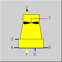
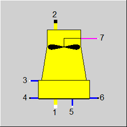
Line connections |
|
|
|
1 |
Air inlet |
|
|
2 |
Air outlet |
|
|
3 |
Cooling water inlet |
|
|
4 |
Cooling water outlet |
|
|
5 |
Make-Up water inlet |
|
|
6 |
Blow-Down |
|
|
7 |
Fan power |
|
General User Input Values Characteristic Lines Physics Used Displays Example
The component forced draft cooling tower simulates the performance of wet cooling towers with induced draft fans under nominal and off-design conditions. A characteristic diagram describes the cooling tower performance.
Deviating from earlier versions, an additional switch (FCHRX) allows using the inlet air wet bulb temperature for the look-up in the performance nomograph. This corresponds with the definitions set out in DIN 1947. For legacy reasons and compliance with earlier versions of EBSILON, it is possible to (incorrectly) use the air dry bulb temperature (T1).
Characteristic Diagram
The basis of the characteristic diagram is the German industrial standard DIN 1947 (version of May 1989). The detailed structure of the description is taken from page 11 of this standard. The main purpose of DIN 1947 is to support cooling tower acceptance tests; consequently, the characteristic diagram only covers a narrow range of operation.
The characteristic diagram defines the cooling range or cold water temperature as a function of
- air wet bulb temperature,
- relative fan power,
- relative water mass flow rate and
- warm water inlet temperature.
Ten (10) characteristic curves, organized in three (3) curve sets, describe the performance nomograph. All curve sets are plotted in the same x-y-diagram with the wet bulb temperature as x-axis and the warm water inlet temperature (TWARM) as y-axis. The following curves need to be defined:
- 2 characteristic curves for the relative fan power QRFAN_1 and QRFAN_2 each with 2 points (linear dependency)
- 2 characteristic curves for load-factors LOAD_1 and LOAD_2 each with 2 points (linear dependency)
- 6 characteristic curves for cooling range CR_1-CR_6 each with 6 points (non-linear dependency)
The actual values of the parameters: relative fan power, relative water flow rate and cooling range must be within the definition range of the curves. Thus
- Min (QRFAN_1, QRFAN_2) <= H7 <= Max (QRFAN_1, QRFAN_2)
- Min (LOAD_1, LOAD_2) <= M3/M3N <= Max (LOAD_1, LOAD_2)
- CR_1 <= Cooling Range <= CR_6
If inputs exceed these limits, the limits are taken as input parameters. Otherwise, a linear interpolation is done. No extrapolation will be done; all returning values will be kept between the MIN and MAX constraints.
This switch permits the use of different off-design states.
FMODE = 2: Calculation of the cooling tower performance, using the performance nomograph
FMODE = 0: Design calculation by defining the cold water temperature (T4CN). The warm water temperature is set to T3 (T3N=T3). The air temperature is taken from line 1. The relative fan power is set to 100% and relative cooling water flow rate is set to 100%. The cooling range is calculated using inlet water temperature (T3) and the user input for the cold water temperature (T4CN). A characteristic cooling range is calculated, using the nomograph. CCR (Cooling range correction) is calculated and stored as the difference between the cooling range from the design calculation and the characteristic cooling range from the performance nomograph.
FMODE = 1: Off-design case using characteristic diagram and CCR-correction determined by the reference conditions. The cooling range is determined by the nomograph and is corrected with CCR (actual cooling range = cooling range from the characteristic diagram + CCR). This operation represents a parallel shift of the characteristic curve.
FMODE = -1 (identification mode): T4 is given from outside, the cooling range is calculated using T3 and T4. The characteristic diagram is not used.
FCHRX
This switch defines which temperature value of the incoming air will be used for the look-up procedure in the performance nomograph.
FCHRX = 0 Look-Up is carried out using the air dry bulb temperature (=T1).
FCHRX = 1 Look-Up is carried out using the air wet bulb temperature.
FSPECL
For this component, the physical behaviour is determined by a characteristic field. Outside this field, results may occur which are physically not reasonable. In Release 8.00, a mechanism was implemented that restricts the temperature to the range of the characteristic field. This action may yield to different results compared to Release 7.00. If this change has to be avoided, you can deactivate the restriction by deactivating the flag FSPECL in the property sheet of the cooling tower.
T4 specification
For the identification mode (T4 specification) there are result values T3CL and T3CLCCR indicating which hot water temperature would arise due to the characteristic field to the width of the cooling section specified from outside. Here T3CL takes the unchanged characteristic field as a basis, and T3CLCCR the characteristic field corrected by the offset CCR.
Blow down
The mass flow for the blow down water can be specified externally now.
Identification Mode
It is possible to specify the cold water temperature T4 from outside (FMODE=-1). The cooling range will be calculated in this case.
Adaptation Polynomial ADAPT / Adaptation function EADAPT
Either the cooling range or the cold water temperature can be calculated or corrected with an adaptation polynomial or adaptation function.
Notes:
For this component, the physical behaviour is determined by a characteristic field. Outside this field, results may occur which are physically not reasonable. In Release 8.00, a mechanism was implemented that restricts the temperature to the range of the characteristic field. This action may yield to different results compared. If this change has to be avoided, you can deactivate the restriction by deactivating the flag FSPECL in the property sheet of the cooling tower.
There may be situations where it is not possible to close the energy balances based on the settings. Often, this was caused by a high setting for the spray losses. Therefore, in Ebsilon Release 9, the spray losses were reduced automatically (with a warning). On customer’s wish, this automatic reduction was removed (as of Release 10). Instead, the air mass flow was restricted to a plausible range between 0.2 and 5 of the cooling water mass flow (with a warning as well).
This may cause small changes in the results (mass flow, water fraction) on the air side.
|
T4CN |
Cold water temperature (nominal) |
|
DP34N |
Pressure loss line 34 (nominal)
Optional input, in case left empty, both pressures must be specified outside. |
|
MSM3 |
Drift loss fraction (MS/M3) |
|
M6M3 |
Blow Down fraction (M6/M3)
Optional input, in case left empty, the blow down mass flow must be specified outside. |
|
FMODE |
Flag for calculation mode Expression =0: GLOBAL =1: local off-design with normalized performance nomograph =2: Use performance nomograph = -1: T4-specification from outside |
|
FSPEC |
Flag for make-up mode Expression =0: Circulation mode i.e. M3=M4 and M5=M2-M1+M6 =1: Discharge mode i.e. M4=M3-(M2-M1+M6) and M5=0 |
|
FCHRX |
X value of characteristic Expression = 0: Ordinary air temperature = 1: Wet bulb temperature |
|
FSPECL |
Temperature limitations Expression =0: No limitation =1: Temperature restricted according to characteristic field |
|
FADAPT |
Flag for using the adaptation polynomial ADAPT / adaptation function EADPT Expression =0: not used and not evaluated =1: CR = Polynomial * CR from performance nomograph =2: CR = Polynomial =3: T4 = T4CN*Polynomial =1000: Not used, but ADAPT evaluated as RADAPT (Reduction of the computing time) = -1: CR = adaptation function * CR from performance nomograph = -2: CR = adaptation function = -3: T4 = T4CN * adaptation function = -1000: Not used, but EADAPT evaluated as RADAPT (Reduction of the computing time) |
|
EADAPT |
Adaptation function |
|
QRFAN_1 |
Characteristic curve parameter relative fan power 1 |
|
QRFAN_2 |
Characteristic curve parameter relative fan power 2 |
|
LOAD_1 |
Characteristic curve parameter M3/M3N_1 |
|
LOAD_2 |
Characteristic curve parameter M3/M3N_2 |
|
CR_1 |
Characteristic curve parameter cooling range 1 |
|
CR_2 |
Characteristic curve parameter cooling range 2 |
|
CR_3 |
Characteristic curve parameter cooling range 3 |
|
CR_4 |
Characteristic curve parameter cooling range 4 |
|
CR_5 |
Characteristic curve parameter cooling range 5 |
|
CR_6 |
Characteristic curve parameter cooling range 6 |
|
QFANN |
Fan power (nominal) |
|
T1N |
Temperature at air inlet (nominal) |
|
T3N |
Warm water temperature (nominal) |
|
CCR |
Correction of the cooling range |
|
M1N |
Air mass flow (nominal) |
|
M3N |
Cooling water mass flow (nominal) |
The identification value marked in blue is a reference value for off-design calculations. The actual off-design values refer to the values used in the equations.
Generally, all inputs that are visible are required. But, often default values are provided.
For more information on colour of the input fields and their descriptions see Edit Component\Specification values
For more information on design vs. off-design and nominal values see General\Accept Nominal values
|
Characteristic curve: Warm water (T3) characteristic curve: T3=f(T1,QRFAN_1) |
|
X-axis 1 T1 1st point |
|
Characteristic curve: Warm water (T3) characteristic curve: T3=f(T1,QRFAN_2) |
|
X-axis 1 T1 1st point
|
|
Characteristic curve: Warm water (T3) characteristic curve: T3=f(T1,LOAD_1) |
|
X-axis 1 T1 1st point |
|
Characteristic curve: Warm water (T3) characteristic curve: T3=f(T1,LOAD_2) |
|
X-axis 1 T1 1st point |
|
Characteristic curve: Warm water (T3) characteristic curve: T3=f(T1,CR_1) |
|
X-axis 1 T1 1st point |
|
Characteristic curve: Warm water (T3) characteristic curve: T3=f(T1,CR_2) |
|
X-axis 1 T1 1st point |
|
Characteristic curve: Warm water (T3) characteristic curve: T3=f(T1,CR_3) |
|
X-axis 1 T1 1st point |
|
Characteristic curve: Warm water (T3) characteristic curve: T3=f(T1,CR_4) |
|
X-axis 1 T1 1st point |
|
Characteristic curve: Warm water (T3) characteristic curve: T3=f(T1,CR_5) |
|
X-axis 1 T1 1st point |
|
Characteristic curve: Warm water (T3) characteristic curve: T3=f(T1,CR_6) |
|
X-axis 1 T1 1st point |
|
All cases |
||
|
|
Moisture ======== MOL:= Molar mass Y1H2O = X1H2O*MOL1SUM/18.0152 P1S = fsat(T1) PHI1 = Y1H2O*P1/P1S
LOAD = M3/M3N
if (FMODE=2), then { off-design with characteristic curve }
if (GLOBAL = design and FMODE = GLOBAL), then { Design case LOAD=1 }
if (GLOBAL = off-design or FMODE=1), then { off-design with normalized performance nomograph }
Characteristic diagram interpolation ============================
Interpolation moisture WW1 = f(T1) from characteristic curve 1 with QRFAN_1 WW2 = f(T1) from characteristic curve 2 with QRFAN_2 ZW = WW1+(H7-QRFAN_1)/( QRFAN _2- QRFAN _1)*(WW2-WW1)
Interpolation load WW1 = f(ZW) from characteristic curve 3 with LOAD_1 WW2 = f(ZW) from characteristic curve 4 with LOAD_2 ZW = WW1+(LOAD-LOAD_1)/(LOAD_2-LOAD_1)*(WW2-WW1)
Interpolation warm water temperature WW1 = f(ZW) from characteristic curve 5 with CR_1 WW2 = f(ZW) from characteristic curve 6 with CR_2 WW3 = f(ZW) from characteristic curve 7 with CR_3 WW4 = f(ZW) from characteristic curve 8 with CR_4 WW5 = f(ZW) from characteristic curve 9 with CR_5 WW6 = f(ZW) from characteristic curve 10 with CR_6
if (T3 >= WW(I) UND T3 < WW(I+1)), then { ZW = (WW(I+1)-WW(I)) CR = CR_(I)+[T3-WW(I)] / ZW * [CR_(I+1)-CR_(I) ] }
T4-calculation =================
if (FMODE=2), then { T4 = T3-CR}
else { if (GLOBAL = design and FMODE = GLOBAL), then { T4 = T4CN ZW = T4N-T3N CCR = ZW-CR }
else { ZW = CCR+CR T4 = T3-ZW } }
State 4 =======
HX4 = f(P4,T4) HX6 = HX4
Approximation state 2 =====================
FAC = .8 T2 = FAC*T3+(1-FAC)*T4 P2S = fsat(T2) Y2H2O = P2S/P2 XH2O = Y2H2O*18.0152/MOL1SUM DSR = XH2O-X1H2O MSM1 = M3*MSM3/M1
M2M1 = 1+DSR+MSM1 X2H2OG = XH2O/M2M1
ZW = 1/M2M1 X2H2OL = MSM1*ZW
if ( i != H2O), then { X2i=X1i*ZW }
HX2 = f(P2,T2)
Calculation of M1 =================
H2_1 = f(P1,T2) H2_2 = f(P3,T2)
if (FSPEC = 0), then { ZW = HX2_1-H1+DSR*(H2_2-H4) M1 = M3*(H3-H4)/ZW } else { ZW = H2_1-H1+DSR*(H2_2-H4) MX1 = M3*(H3-H4)/ZW }
Pressure equations =================
F = (M3/M3N) ** 2 DP34 = DP34N * F P4 = P3 - DP34 P2 = P1 P4 = P6 P4 = P5
Enthalpy equations ===================
H2 = HX2 H4 = HX4 H6 = HX6
Mass flow equations ======================
if FSPEC=0, then { M3 = M4 } else { M3*(M6M3+MSM3)+DSR*M1 = M4 }
M1 = MX1 M2 = M2M1*M1 M6 = M6M3*M3
if FSPEC=0, then { M5 = (M6M3+ MSM3)*M3+DSR*M1 } else { M5 = 0 }
|
|
 |
Display Option 1 |
Click here >> Component 79 Demo << to load an example.