
|
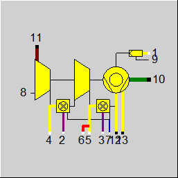
Line connections |
|
|
|
1 |
Ambient air inlet |
|
|
2 |
SEV-Burner fuel inlet |
|
|
3 |
EV-Burner fuel inlet |
|
|
4 |
Low pressure air inlet |
|
|
5 |
High pressure air inlet |
|
|
6 |
Steam injection |
|
|
7 |
Water inlet for NOx reduction |
|
|
8 |
Load |
|
|
9 |
Anti-icing switch |
|
|
10 |
Outlet of mechanical shaft |
|
|
11 |
Flue gas outlet |
|
|
12 |
Low pressure air outlet |
|
|
13 |
High pressure air outlet |
|
General User Input Values Physics Used Displays
Component 76 is a component with external calculation. This means that the calculation is not done by EBSILON®Professional, but else by an external program (Dll), which the customer must provide.
Without this program, it is not possible to include this component to your cycle.
Component 76 was developed together with ABB (later Alstom) to integrate Alstom reheat gas turbines in EBSILON®Professional.
EBSILON®Professional provides the framework for the calculation while the calculation itself is done by an internal Alstom program.
|
DPIN |
Input of pressure loss |
|
DPOUT |
Output of pressure loss |
|
FCOOL |
Air cooler Expression =-1: OTC = 0: Quench-cooler |
|
FFUEL |
Fuel type Expression =1: Fuel components oil =2: Fuel components gas =4: Isomethane =5: Diesel No. 2 |
|
FMTYPE |
Machine type Expression =0: GT24 =1: GT26 |
|
T1 |
Ambient air temperature |
|
PHI1 |
Ambient air humidity |
|
P1 |
Ambient pressure |
|
UN1 |
Unused P-MAP input |
|
FICE |
Anti icing switch |
|
M6 |
Mass flow of steam injection |
|
T6 |
Temperature of steam injection |
|
P6 |
Pressure of steam injection |
|
GTLOAD |
Gas turbine load |
|
GTPOWF |
Generator power factor |
|
UN2 |
Unused P-MAP input |
|
UN3 |
Unused P-MAP input |
|
T3 |
EV burner fuel gas temperature |
|
T2 |
SEV burner fuel gas temperature |
|
T7 |
Temperature of the NOx water injection |
|
P7 |
Pressure of the NOx water injection |
|
UN4 |
Unused P-MAP input |
|
UN5 |
Unused P-MAP input |
The parameters marked in blue are reference quantities for the off-design mode. The actual off-design values refer to these quantities in the equations used.
Generally, all inputs that are visible are required. But, often default values are provided.
For more information on colour of the input fields and their descriptions see Edit Component\Specification values
For more information on design vs. off-design and nominal values see General\Accept Nominal values
|
All cases |
||
|
|
The following values are specified by start and boundary values:
- M1, M6 - P1, P4, P5, P6, P7, P11, P12, P13 - H1, H2, H3, H6, H7, H8, H9
M2 from the user program M3 from the user program M4 from the user program M5 from the user program M7 from the user program
M8 = 1.0 M9 = 1.0
M10 = 1.0
M11 from the user program M12 = M5 M13 = M4
P2 from the user program P3 from the user program
P8 = 0.02 P9 = 0.02 P10 = 0.02
H4 for P4 and T4, T4 from the user program
H5 for P5 and T5, T5 from the user program
H10 from the user program
H11 for P11 and T11, T11 from the user program
QHP, QLP from the user program
H12 = (QHP + M5 * H5) / H5
H13 = (QLP + M4 * H4) / H4
|
|
 |
Display Option 1 |
There is no example available.