EBSILON®Professional Online Documentation


|
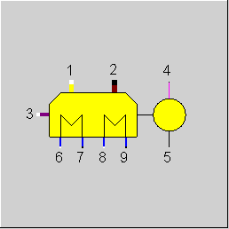
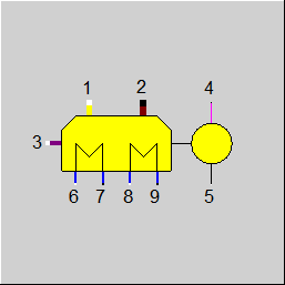
Line connections |
|
|
|
1 |
Air inlet |
|
|
2 |
Flue gas outlet |
|
|
3 |
Fuel inlet |
|
|
4 |
Power output at generator terminals |
|
|
5 |
Regulating information for power output |
|
|
6 |
Inlet heat loop 1 |
|
|
7 |
Outlet heat loop 1 |
|
|
8 |
Inlet heat loop 2 |
|
|
9 |
Outlet heat loop 2 |
|
General User Input Values Characteristic Lines Physics Used Displays Example
Component 74 does not calculate the individual aggregates of the block heating power plant, but instead uses all values from characteristic fields that must be provided by the manufacturer of the machine. In this way, it is assured that the specifications of the manufacturer remain unchanged during the calculation. This allows a good adaptation to the warranty conditions.
The flue gas composition is determined by a combustion calculation under consideration of the air ratios and fuel analysis.
The flue gas temperature is calculated by using the values of the characteristic fields and the energy balance.
As a heat transfer medium for the block-type thermal power station (heating circuit 1 and heating circuit 2), all substances can be used in both heating circuits (see also material value input).
Specification of voltage, frequency and type of current in the component:
There is the option of specifying the voltage (VOLT), frequency (FREQ) and type of current (NPHAS) as the default value in the component.
The flags FVOLT and FFREQ are used to set whether the specification is to be made by the new specification values VOLT and FREQ respectively (0) or externally as a measured values on the electrical line (-1).
|
FMODE |
Flag for calculation mod Like in Parent Profile (Sub Profile option only) =0: GLOBAL =1: local off-design |
|
ALAM |
Air ratio (air to air stoichiometric) |
|
DP67N |
Pressure loss line 6 to 7 (nominal) |
|
DP89N |
Pressure loss line 8 to 9 (nominal) |
|
T7MAX |
Maximum of the outlet temperature line 7 |
|
T9MAX |
Maximum of the outlet temperature line 9 |
|
T2MIN |
Minimum of the outlet temperature line 2 |
|
T2MAX |
Maximum of the outlet temperature line 2 |
|
FVOLT |
Flag for the method for specification of voltage Like in Parent Profile (Sub Profile option only) Expression =0: Defined by specification value VOLT =-1: Voltage given externally on electrical outlet |
|
VOLT |
Voltage (on electric lines) |
|
FFREQ |
Flag for the method for specification of frequency Like in Parent Profile (Sub Profile option only) Expression =0: Use specification value FREQ =-1: Frequency given externally on electrical outlet |
|
FREQ |
Generator frequency |
|
NPHAS |
Type of current Like in Parent Profile (Sub Profile option only) Expression =0: Direct current =1: One-phase alternating |
|
QN |
Nominal power |
|
M6N |
Mass flow in the line 6 and 7 |
|
M8N |
Mass flow in the line 8 and 9 |
|
V6N |
Specific volume at inlet 6 |
|
V8N |
Specific volume at inlet 8 |
The identification values marked in blue are reference quantities for the off-design mode. The actual off-design values refer to these quantities in the equations used.
Generally, all inputs that are visible are required. But, often default values are provided.
For more information on colour of the input fields and their descriptions see Edit Component\Specification values
For more information on design vs. off-design and nominal values see General\Accept Nominal values
|
Characteristic line 1, CQ3NCV : Demand of fuel heat Q3NCV / Q5 = f(Q5/QN) |
|
X-axis 1 Q5 / QN 1st point |
|
Characteristic line 2, CQ67: Heat absorption of cooling 1 Q67 / Q5 = f(Q5/QN) |
|
X-axis 1 Q5 / QN 1st point |
|
Characteristic line 3, CQ89: Heat absorption of cooling 2 Q89 / Q5 = f(Q5/QN) |
|
X-axis 1 Q5 / QN 1st point |
|
Characteristic line 4, CQLOSS : Heat loss QL / Q5 = f(Q5/QN) |
|
X-axis 1 Q5 / QN 1st point
|
|
Design case (Simulation flag: GLOBAL = Design case AND FMODE = Design case) |
||
|
|
The following values are specified by start and boundary values { - all pressures - the composition of flow 1, 3 - the composition of flow 2 is calculated from the measurement of the balances of the mass flows 1, 3 }
M3 from characteristic line fuel energy requirement Q3NCV / Q5 = f(Q5/QN) characteristic line 1 M3 = QN * Q3NCV/Q5 / NCV3
M1 from combustion calculation M1 = M3 * f(X1i,X3i,ALAM)
M2 from mass balance M2 = M1 + M3
M6 = M7
M8 = M9 M4 = 1.0 M5 = 1.0
M6R = M6/M6N F1 = (M6R ** 2) * (V6/V67N) if GLOBAL = design, then F1= 1.0
DP67 = DP67N* F1 P7 = P6 DP67
M8R = M8/M8N F2 = (M8R ** 2) * (V8/V89N) if GLOBAL = design, then F2= 1.0
DP89 = DP89N* F2 P9 = P8 DP89 P4 = 0.01 P5 = 0.01
Remaining heat in the flue gas Q3D = Q3NCV Q2 = Q1 + Q3 + Q3D-(Q4 + Q67 + Q89 + QL) (with Q67, Q89, QL from characteristic lines)
H2 = Q2/M2
M7*H7-M6*H6=Q67
M9*H9-M8*H8=Q89
H4 = H5
|
|
 |
Display Option 1 |
Click here >> Component 74 Demo << to load an example.