
|
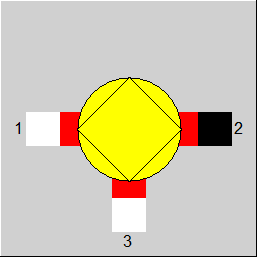
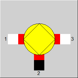
Line connections |
|
|
|
1 |
Fluid inlet |
|
|
2 |
Fluid outlet |
|
|
3 |
Admixture |
|
General User Input Values Physics Used Displays Example
Component 60 is a mixer that can be use in different ways:
The advantage of this component is the possibility to modify its behaviour via specification values. Therefore, it can be modified in sub profiles and in EbsScript.
The setting of these flags may be important for the convergency behaviour. More general specifications are more difficult for the convergency. Example: if there are convergency problems with the setting FSPECM= "M1 or M2 or M3 given" and you know that M3 is known in your model, it is worth to change the setting to "M3 given".
In analogy to FSPECP, FSPECH, and FSPECM there is a FSPECX . It allows defining on which pins a composition is to be specified. However, this flag can only be used if the material equations are integrated into the equation system. (Model options --> Simulation --> Iteration, Level of integration of material equations)
Notes: Mixing of fluids
The treatment of lines of the types “air“, “flue gas“, “gas“, “crude gas“, “coal”, “oil“, and “user-defined“ has been standardized, so that nearly the same substances can be present in each line. The substances added due to this, however, are displayed further below in the combo box, so that the handling during the input does not change.
This standardization allows mixing different fuels (e.g. oil and gas). Both Component 60 (General mixer) and Component 28 (Tank (mixing point)) can be used for this. The advantage is that due to this it is no longer necessary to model a separate combustion chamber for different fuel types in each case.
Treatment of the Voltage
Previously, the voltage on the outlet line (U2) was equated with that on the main inlet line (U1) and it was checked whether the voltage on the auxiliary inlet line (U3) was consistent with it.
Due to the expansion of the options in dealing with electric lines in the context of implementing Component 158, it turned out that it makes sense to implement different variants for passing on the voltage. The switchover between the variants is effected by means of a flag FSPECU:
Component 37 (Mixer without throttling at line 3):
In component 37, the main mass flow 1 and the auxiliary mass flow 3 are brought together. It is assumed that there is no throttling of the pressure of the main mass flow in the component, which means the pressure of the auxiliary mass flow is identical to the pressure of the main mass flow. It is taken from the main mass flow. In the auxiliary mass flow, only the enthalpy and the flow rate have to be defined.
Component 3 (Mixer with throttle at line 3):
An alternative component is component 3, where the auxiliary mass flow is throttled, which means the pressure of the auxiliary mass flow has to be set and must be larger than the pressure of the main mass flow.
|
M3M2 |
Ratio of the mass flows: M3/M2 |
|
FSPECP |
Flag for pressure handling
Like in Parent Profile (Sub Profile option only) Expression =10: P2=P1, (P1 or P2) and P3 given =11: P2=P1, P1 and P3 given =12: P2=P1, P2 and P3 given =20: P1=P2=P3, P1 or P2 or P3 given =21: P1=P2=P3, P1 given =22: P1=P2=P3, P2 given =23: P1=P2=P3, P3 given =30: P2=P3, (P2 or P3) and P1 given =32: P2=P3, P2 and P1 given =33: P2=P3, P3 and P1 given =100: P2=min(P1,P3), P1 and P3 given =101: P2=min(P1,P3), P1 and (P2 or P3) given =103: P2=min(P1,P3), P3 and (P1 or P2) given =200: P2=min(P1,P3), if M1 and M3>0, P1 and P3 given =0: (old mode) P2=min(P1,P3) =1: (old mode) P1 = P2 = P3 =2: (old mode) P2=min(P1,P3) if M1 and M3 >0 |
|
FSPECH |
Flag for enthalpy handling
Like in Parent Profile (Sub Profile option only) Expression =10: H1=H2=H3, 1 of 3 given =11: H1=H2=H3, H1 given =12: H1=H2=H3, H2 given =13: H1=H2=H3, H3 given =200: any 2 given =213: H2 calculated from H1 and H3 =212: H3 calculated from H1 and H2 =223: H1 calculated from H2 and H3
=0: (old) H2 calculated from H1 and H3 =1: (old) H2 specified, (H1=H3=H2) =2: (old) H3 calculated from H1 and H2. |
|
FSPECM |
Flag for mass flow handling
Like in Parent Profile (Sub Profile option only) Expression =0: any 2 given =1: M1 and (M2 or M3) specified =2: M2 and (M1 or M3) specified =3: M3 and (M1 or M2) specified =12: M1 and M2 specified =23: M2 and M3 specified =13: M1 and M3 specified =100: M1 or M2 or M3 specified =101: M1 specified =102: M2 specified =103: M3 specified |
|
FSPECX |
Material-equation handling
Like in Parent Profile (Sub Profile option only) Expression =0: Any given =1: Pins 1 and (2 or 3) given =2: Pins 2 and (1 or 3) given =3: Pins 3 and (1 or 2) given =12: Pins 1 and 2 given =23: Pins 2 and 3 given =13: Pins 1 and 3 given |
Generally, all inputs that are visible are required. But, often default values are provided.
For more information on colour of the input fields and their descriptions see Edit Component\Specification values
For more information on design vs. off-design and nominal values see General\Accept Nominal values
|
All cases |
||
|
|
M2 = M1 + M3 M3 = M2 * M3M2 (This equation is not used if M3M2 is not specified)
for FSPECP=0: P2 = P1 if P1 < P3 P2 = P3 if P1 > P3
for FSPECP=1: P1 = P2 P3 = P2
for FSPECP=2: P2 = P1 if P1 < P3 and M1 > 0.001*M3 P2 = P3 if P1 > P3 and M3 > 0.001*M1
for FSPECH=0: H2*M2 = H1*M1 + H3*M3
for FSPECH=1: H1 = H2 H3 = H2 T2 = f (P2,H2) If wet steam is present at line 2, then X2 = f(P2,H2) Q2 = Q1 + Q3 NCV2 = (NCV1 * M1 + NCV3 * M3) / M2 |
|
 |
Display Option 1 |
 |
Display Option 2 |
Click here >> Component 60 Demo << to load an example.