
|
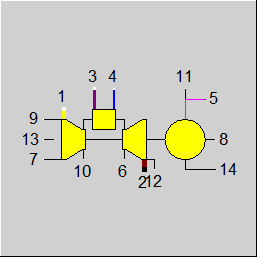
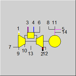
Line connections |
|
|
|
1 |
Air inlet |
|
|
2 |
Exhaust gas outlet |
|
|
3 |
Fuel inlet |
|
|
4 |
Injection water / steam inlet |
|
|
5 |
Generator power |
|
|
6 |
Inlet for TIT-controller |
|
|
7 |
Inlet for controlling VIGV (through component 46, type 8) |
|
|
8 |
Inlet for controlling COS-PHI (through component 46, type 8) |
|
|
9 |
Measurement value (P, T) for compressor inlet |
|
|
10 |
Measurement value (P, T) for compressor outlet |
|
|
11 |
Measurement value (Q) for generator terminals |
|
|
12 |
Measurement value (P,T) for turbine outlet |
|
|
13 |
Measurement value (P) for atmospheric pressure |
|
|
14 |
Outlet for base-load (through component 46, type 9) |
|
|
|
|
|
General User Input Values Characteristic Lines Physics Used Displays Example
Component 57 simulates the complete operation behaviour of a gas turbine in the vicinity of the design point. The following values are calculated with the help of characteristic diagrams:
In the characteristic diagrams (comprising of 241 characteristic lines), there are dependencies of the following values
These must be defined. This data is specific for the type.
The component also has a series of logic connections, on which the following values can be specified as measurement values:
Measuring values are assigned by component 46, (measured value input component).
The following values are determined through measurement values and characteristic lines:
As such, specific values can be formed from the values given above.
It is expected, that the turbine inlet temperature is given or regulated by "Temperature", which lies at line-connection 6 (e.g. to deliver a demanded power).
The position of the first blade row is given and regulated by setting a component 46 on line-connection 7 specified as type 8. VIGV can be given as "POSITIVE" or "NEGATIVE" value.
COS-PHI of the generator is given and regulated by setting a component 46 on line-connection 7 specified as type 8.
The base-load factor is given by setting a component 46 on line-connection 8 specified as type 9.
|
QN |
Gas turbine power (nominal) |
|
ETGN |
Total efficiency gas turbine (nominal) |
|
M1N |
Mass flow of air (nominal) |
|
TEXN |
Exhaust gas temperature (nominal) |
|
DPIN |
Inlet pressure loss |
|
DPOUT |
Outlet pressure loss |
|
REV |
Rotary speed |
|
DQLGG |
Sum of gear and generator losses |
|
RQLCC |
Relative combustion chamber heat loss |
|
RDPCC |
Relative combustion chamber pressure loss |
|
TITB |
Base load turbine inlet temperature |
|
FDP |
Type of DP calculation =1: Calculate DPIN and DPOUT with simulation =2: Input DPIN, Calculation DPOUT =3: Input DPOUT, calculation DPIN =4: Input DPIN and DPOUT |
|
FPEBS |
(removed) |
Generally, all inputs that are visible are required. But, often default values are provided.
For more information on colour of the input fields and their descriptions see Edit Component\Specification values
For more information on design vs. off-design and nominal values see General\Accept Nominal values
Notes for using FDP
--------------------------------------------------------------------
FDP is a selection index for taking into account different inputs for determining the inlet and the outlet pressure losses (DPIN, DPOUT)
=1: Calculation of
Inlet and outlet pressure loss through simulation results
DPIN = P(MEDIUM) - P(Inlet) = P13 - P1
DPOUT = P(Outlet) - P(MEDIUM) = P2 - P13
=2: Calculation of
Inlet pressure loss through user input values, and
outlet pressure loss through simulation results
DPIN = DPIN
DPOUT = P(outlet) - P(MEDIUM) = P2 - P13
and calculation of P1=P13-DPIN
=3: Calculation of
outlet pressure loss through user input value, and
inlet pressure loss through simulation results
DPIN = P(MEDIUM) - P(inlet) = P13 - P1
DPOUT = DPOUT
and calculation of P2=P13+DPOUT
=4: Calculation of
outlet and inlet pressure loss through user input values
DPIN = DPIN
DPOUT = DPOUT
and calculation of P1=P13-DPIN
and calculation of P2=P13+DPOUT
Terms
=======
TIT Turbine inlet temperature
T0 average temperature
P0 average pressure
DPIN Inlet pressure loss
DPOUT Outlet pressure loss
COSP COS-PHI of the generator
STEL Position of the leading blades
WSBN Water injection
Q Generator power
QN Nominal value of generator power
ETG Total efficiency
ETAN Nominal value of total efficiency
DL Air mass flow
DL1N Nominal value of air mass flow
TA Turbine exhaust gas temperature
TABN Nominal value of exhaust gas temperature
PIK Compressor pressure ratio
ETAC Compressor efficiency
ETAT Turbine efficiency
VIGV Position of the inlet valves
Generator power
===============
Q = QN * QF0 * QF1 * QF2 * QF3 * QF4 * QF5 * QF6 * QF7
QF0 = f (TIT) characteristic line 232
Characteristic diagram 1 : QF1 = f (T0 ,TIT)
characteristic line 1 to 7
Characteristic diagram 2 : QF2 = f (P0 ,TIT)
characteristic line 8 to 14
Characteristic diagram 3 : QF3 = f (DPIN,TIT)
characteristic line 15 to 21
Characteristic diagram 4 : QF4 = f (DPOT,TIT)
characteristic line 22 to 28
Characteristic diagram 5 : QF5 = f (COSP,TIT)
characteristic line 29 to 35
Characteristic diagram 6 : QF6 = f (STEL,TIT)
characteristic line 36 to 42
Characteristic diagram 7 : QF7 = f (WSBN,TIT)
characteristic line 43 to 49
Parameter is the TIT with
750, 800, 900, 1000, 1100, 1125, 1150 °C
Total efficiency
================
ETG = ETAN * EF0 * EF1 * EF2 * EF3 * EF4 * EF5 * EF6
EF0 = f (TIT) characteristic line 233
Characteristic diagram 8 : EF1 = f (T0 ,TIT)
characteristic line 50 to 56
Characteristic diagram 9 : EF2 = f (DPIN,TIT)
characteristic line 57 to 63
Characteristic diagram 10 : EF3 = f (DPOT,TIT)
characteristic line 64 to 70
Characteristic diagram 11 : EF4 = f (COSP,TIT)
characteristic line 71 to 77
Characteristic diagram 12 : EF5 = f (STEL,TIT)
characteristic line 78 to 84
Characteristic diagram 13 : EF6 = f (WSBN,TIT)
characteristic line 85 to 91
Parameter is the TIT with
750, 800, 900, 1000, 1100, 1125, 1150 °C
Air mass flow
=============
M1 = M1N * MF0 * MF1 * MF2 * MF3 * MF4 * MF5
MF0 = f (TIT) characteristic line 234
Characteristic diagram 14 : MF1 = f (T0 ,TIT)
characteristic line 92 to 98
Characteristic diagram 15 : MF2 = f (P0 ,TIT)
characteristic line 99 to 105
Characteristic diagram 16 : MF3 = f (DPIN,TIT)
characteristic line 106 to 112
Characteristic diagram 17 : MF4 = f (STEL,TIT)
characteristic line 113 to 119
Characteristic diagram 18 : MF5 = f (WSBN,TIT)
characteristic line 120 to 126
Parameter is the TIT with
750, 800, 900, 1000, 1100, 1125, 1150 °C
Exhaust gas temperature
=======================
TA = TABN + TF0 + TF1 + TF2 + TF3 + TF4 + TF5 + TF6
TF0 = f (TIT) characteristic line 235
Characteristic diagram 19 : TF1 = f (T0 ,TIT)
characteristic line 127 to 133
Characteristic diagram 20 : TF2 = f (P0 ,TIT)
characteristic line 134 to 140
Characteristic diagram 21 : TF3 = f (DPIN,TIT)
characteristic line 141 to 147
Characteristic diagram 22 : TF4 = f (DPOT,TIT)
characteristic line 148 to 154
Characteristic diagram 23 : TF5 = f (STEL,TIT)
characteristic line 155 to 161
Characteristic diagram 24 : TF6 = f (WSBN,TIT)
characteristic line 162 to 168
Parameter is the TIT with
750, 800, 900, 1000, 1100, 1125, 1150 °C
Compressor pressure ratio
=========================
for 22° <= VIGV < 5° : PIK = PK2 - (PK3-PK2)*(VIGV+15)/15
for 5° <= VIGV < 32° : PIK = PK1 - (PK2-PK1)* VIGV/15
Characteristic diagram 25 : PK1 = f (T0,TIT)
characteristic line 169 to 175 for VIGV= 32°
Characteristic diagram 26 : PK2 = f (T0,TIT)
characteristic line 176 to 182 for VIGV= 5°
Characteristic diagram 27 : PK3 = f (T0,TIT)
characteristic line 183 to 189 for VIGV=-22°
Parameter is TIT with
750, 800, 900, 1000, 1100, 1125, 1150 °C
Compressor efficiency
=====================
for 22° <= VIGV < 5° : ETAC = ETAC2 - (ETAC3-ETAC2)*(VIGV+15)/15
for 5° <= VIGV < 32° : ETAC = ETAC1 - (ETAC2-ETAC1)* VIGV/15
Characteristic diagram 28 : ETAC1 = f (T0,PIK)
characteristic line 190 to 196 for VIGV= 32ø
Characteristic diagram 29 : ETAC2 = f (T0,PIK)
characteristic line 197 to 203 for VIGV= 5ø
Characteristic diagram 30 : ETAC3 = f (T0,PIK)
characteristic line 204 to 210 for VIGV=-22ø
Parameter is PIK
14.8, 15.0, 15.2, 15.6, 16.0, 16.4, 16.8
Turbine efficiency
==================
for 22° <= VIGV < 5° : ETAT = ETAT2 - (ETAT3-ETAT2)*(VIGV+15)/15
for 5° <= VIGV < 22° : ETAT = ETAT1 - (ETAT2-ETAT1)* VIGV/15
Characteristic diagram 31 : ETAT1 = f (T0,PIK)
characteristic line 211 to 217 for VIGV= 32ø
Characteristic diagram 32 : ETAT2 = f (T0,PIK)
characteristic line 218 to 224 for VIGV= 5ø
Characteristic diagram 33 : ETAT3 = f (T0,PIK)
characteristic line 225 to 231 for VIGV=-22ø
Parameter is PIK
14.8, 15.0, 15.2, 15.6, 16.0, 16.4, 16.8
The characteristic lines 236 to 241 are no longer used.
|
All cases |
||
|
|
Total power Q = QN * QF0*QF1*QF2*QF3*QF4*QF5*QF6*QF7 Total efficiency ETG = ETAN * EF0*EF1*EF2*EF3*EF4*EF5*EF6 Air mass flow M1 = M1N * MF0*MF1*MF2*MF3*MF4*MF5 Exhaust gas temperature T2 = TABN + TF0+TF1+TF2+TF3+TF4+TF5+TF6 M1 = M1 M3 = Q/(ETA*NCV3) M4 = WSBN M2 = M1 + M3 + M4 H2 = f(T2) H5 = Q/M5 with M5=1.0 Exhaust gas composition - Weight fractions line 1, 3 and 4, and - Combustion calculation |
|
 |
Display Option 1 |
 |
Display Option 2 |
Click here >> Component 57 Demo << to load an example.