
|
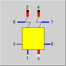
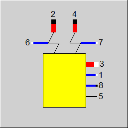
Line connections |
|
|
|
1 |
Feed water inlet |
|
|
2 |
Steam (steam outlet (HD) |
|
|
3 |
Intermediate super heater (IH) inlet |
|
|
4 |
Intermediate super heater (IH) outlet |
|
|
5 |
Heat provided by a connected component 21 |
|
|
6 |
High pressure injection (without throttling) |
|
|
7 |
Intermediate super heater injection (without throttling) |
|
|
8 |
Drain / Blow down |
|
General User Input Values Characteristic Lines Physics Used Displays Example
Component 5 helps in a balanced modeling of the water/steam side of a steam generator. It is used when a detailed modeling of the individual heating surfaces can be avoided. For a detailed modeling the components 26 or 61 (Economizer/Evaporator/Superheater) can be used in simple cases. If a radiation exchange is to be taken into account with the other heating surfaces, the detailed boiler components must be used from the EbsBoiler module (components 88 to 91), which also map the boiler geometry.
Component 5 can be used be together with the component 21 (combustion chamber), in order also to map the flue gas side. The coupling takes place via a controller with the help of logical outlets: Component 5 provides at line 5 the heat requirement by the water/steam side, while the component 21 provides at line 3 the heat generated by the combustion.
Component 5 can model the main-steam production section as well as an intermediate super heating section, often used to represent a reheater. For both the strands an injection can be taken into account. For the high-pressure injection the injection quantity is entered relative to the feed water quantity in the specification value M6M1. For the super heater injection, on the other hand, a characteristic line CM7M1 is used, in which the super heater injection quantity can be entered relative to the feed water quantity. Alternatively, the injection quantities can also be specified externally, e.g. with a measurement point (Component 46) or a start value (Component 33).
Even the drain can be specified selectively via a specification value (relative to the feed water quantity) or externally.
Steam and gaseous two-phase streams can be connected to the main inlet (1) so that this component can also be used for superheating.
CAUTION:
While modeling injections and drains care must be taken to use these with the remaining circulation, as otherwise a violation of the mass balance can occur.
The values T2, P2 and T4 could only be specified either all together by means of specification values or all from outside. There are new options for FSPEC (as of Release 10) to switch one or two of these parameters, too.
When setting the main steam pressure in the component the design pressure is entered as the specification value P2N and the off-design pressure is entered in the slide-pressure characteristic line CP2.
The main steam temperature and the super heater temperature can similarly be set either in the component or can be specified from outside. When setting in the component, the corresponding value, however, is used in all the load cases.
|
P2N |
Main steam pressure (nominal) |
|
T2 |
Main steam temperature |
|
T4 |
Intermediate super heater (reheat) outlet temperature |
|
DP12N |
HP-pressure loss (between ports 1 and 2) (nominal) |
|
DP34N |
Intermediate super heater pressure loss (between ports 3 and 4) (nominal) |
|
M6M1 |
Mass flow ratio of HP injection (always relative to M1) |
|
M8M1 |
Mass flow ratio of drain relative to M1 (in design case relative to M1, in off-design relative to M1N) If you set the specification value M8M1 to -999, the program expects a definition of the drain mass flow given by component 1 (boundary value), component 33 (start value) or component 46 (control measurement point). |
|
DPECON |
Economizer pressure drop (nominal)
This value is used to determine the pressure level of the drain. |
|
FSPEC |
Flag for specifications Like in Parent Profile (Sub profile option only) Expression = 0: T2 as specified, P2 via P2N, T4 as specified
= 1: T2,P2,T4 via component 33 =2: P2 given from outside - T2, T4 internally =3: T2 given from outside - P2, T4 internally =4: T4 given from outside - P2, T2 internally =5: P2, T2 given from outside - T4 internally =6: P2, T4 given from outside - T2 internally =7: T2, T4 given from outside - P2 internally |
|
FVOL |
Part-load pressure drop (reheat only) Like in Parent Profile (Sub profile option only) Expression =0: Calculated from mass (approximation for incompressible fluids) =1: depending on mass and volume flow =2: Constant (equal nominal value) |
|
FMODE |
Flag for calculation mode =0: GLOBAL =1: Local off-design = -1: Local design |
|
FINJ |
Handling of spray and blow down flows
Like in Parent Profile (Sub profile option only) Expression =0: M6, M7 and M8 given by internal specification =1: M6, M7 and M8 given from outside |
|
M1N |
Feed water mass flow (nominal) |
|
V1N |
Specific volume at feed water inlet |
|
M3N |
Mass flow intermediate super heater (nominal) |
|
V3N |
Specific volume at intermediate super heater inlet |
The identification values marked in blue are reference values for off-design mode. These values are referred to for the actual off-design values used in the equations respectively. If these identification values are stream data, then these values are often taken from attached pipes or calculated values.
Generally, all inputs that are visible are required. But, often default values are provided.
For more information on colour of the input fields and their descriptions see Edit Component\Specification values
For more information on design vs. off-design and nominal values see General\Accept Nominal values
Characteristic lines CPD12, CPD34: The default characteristic lines have a constant value of 1.0. A calculation based on physical laws should be more accurate than a default characteristic curve in most cases. In particular, a dependence on the volume flow cannot be taken into account at all in the characteristic line. And to regard steam as an incompressible fluid is probably a rather rough approximation.
|
Characteristic 1 CP2: HP-sliding pressure-characteristic P2/P2N = f(M1/M1N) |
|
X-Axis 1 M1/M1N 1st point |
|
Characteristic 2 CDP12: HP-pressure loss DP12/DP12N = f(M1/M1N) |
|||
|
X-Axis 1 M1/M1N 1st point
|
|
Characteristic 4 CM7M1: IH-injection M7/M1 = f(M1/M1N) |
|
X-Axis 1 M1/M1N 1st point |
|
All cases |
||
|
M1R = M1/M1N (if GLOBAL = nominal load, then M1R= 1.0)
If FSPEC=0, 3, 4 or 7: P2 = f(M1R) * P2N (from the characteristic) otherwise P2 is given from outside
If FSPEC=0, 2, 4 or 6: H2 = f(P2, T2) otherwise H2 is given from outside
M2 = M1 + M6 - M8 Q2 = M2 * H2 M4 = M3 + M7 M3R = M3/M3N If FVOL = 0, then F = (M3R**2) If FVOL = 1, then F = (M3R**2 *(V3/V3N) (If GLOBAL= nominal load, then F = 1.0) DP34 = DP34N * F P4 = P3 - DP34
If FSPEC=0, 2, 3 or 5: H4 = f(P4,T4) otherwise H4 is given from outside
Q4 = M4 * H4 H5 = (M2*Q2 + M4*H4 - M1*H1 - M3*H3 - M6*H6 - M7*H7)/M5
If FINJ=0: M6 = M6M1 * M1 (M7/M2) = f(M1R) (from characteristic) M7 = M1*(M7/M1) M8 = M1N*M8M1
DPHP = f(M1R) * DP12N (from characteristics) P1 = P2 + DPHP P8 = P1 - DPECON * M1R*M1R H8 = Hs(P8)
|
||
|
Relative mass flow feed water |
M1/M1N |
|
Relative mass flow reheat
|
M3/M3N |
|
Relative live steam pressure |
P2/P2N |
|
Relative live steam pressure drop
|
DP12/DP12N |
|
Relative reheat steam pressure drop |
DP34/DP34N |
 |
Display Option 1 |
 |
Display Option 2 |
Click here >> Component 5 Demo << to load an example.