
EBSILON®Professional Online Documentation


|
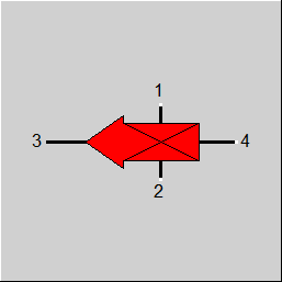
Line connections |
|
|
|
1 |
Signal entry 1 |
|
|
2 |
Signal entry 2 |
|
|
3 |
Signal exit |
|
|
4 |
Measured value input |
|
General User Input Values Characteristic Lines Physics Used Displays Example
This module transfers the signal value S1 or S2 to S3. It depends on the result of the comparison of the two values whether S1 or S2 is transferred.
IN4: Measured value for switch entry according to FSW
IN1: Measured value for signal entry 1 according to FIN
IN2: Measured value for signal entry 2 according to FIN
Pressure, enthalpy or mass flow can be given as input for IN1 and IN2. Pressure, temperature, enthalpy, mass flow or heat flow are permitted as input for the measured value IN4.
For FDC=1 and FDC=-1, the comparison values correspond to the physical values IN4 at the switch entry (line 4) and the scheduled value DVAL, which is defined by a specification value.
For FDC=2 and FDC=-2, the comparison values correspond to the physical values IN1 and IN2 at the signal entries 1 and 2.
The comparison conditions are listed in the table given below.
|
Transmission from ---> to |
FDC |
|||
|
1 |
-1 |
2 |
-2 |
|
|
S1 ---> S3 S2 ---> S3 |
IN4 <= DVAL IN4 > DVAL |
IN4 > DVAL IN4 <= DVAL |
IN1 >= IN2 IN1 < IN2 |
IN1 < IN2 IN1 >= IN2 |
The physical value itself is not transmitted. The transmitted value is (depending on FTR1 or FTR2 respectively) either the relative physical value or a value of a characteristic line with an abscissa formed by the reference physical value. In the first case, the transmitted value is multiplied with a proportional factor.
|
|
Signal entry S1 |
Signal entry S2 |
|
FTR1 |
IN1 ----------- * MUL1 REF1 |
IN2 ----------- * MUL2 REF2 |
|
FTR2 |
IN1 f(-------------) REF1 |
IN2 f(-------------) REF2 |
The physical value OUT3 for the signal exit (line 3) results from the transmission value S3 (this is either S1 or S2) multiplied with a reference value.
OUT3
S3 = ----------
REF3
The dimensions of the switch value and the scheduled value must match with each other. The same also applies to the dimensions of the physical values of the two signal entries.
It is also possible to transfer the temperature. This is useful if the lines involved have different compositions, as otherwise the enthalpy could also be transferred.
However, the options for scaling, using characteristic curves and transferring to another variable are not implemented for temperature transfer in component 48. Due to the special features of the temperature unit conversion, additional information would be required for this, which is, however, implemented in component 36.
For this reason, the FOUT switch and the switches and default values for scaling are inactive when FIN is set to 2.
Hint: If you want to use a switch value of 0, you should be aware of the fact that Ebsilon uses a minimum mass flow of 10^-6 kg/s. To consider the case of no mass flow, a value slightly higher than 10^-6 kg/s should be used.
This component differs from component 48 in that the signal at exit 3 cannot be obtained from one of two entries, but instead is retrieved directly from a signal entry. The input signal can either be the assigned value to a physical value or a characteristic line value calculated with the assigned physical value as abscissa (see component 48). Also, the input signal to be transferred is not multiplied with a proportional multiplication factor, when transmitted by a characteristic line.
Depending on the comparison of two thermodynamic values, either the mass flow of entry 1 or of entry 2 can be transmitted to exit 3. All five thermodynamic values P/T/H/M/Q can be comparative values.
| FFU |
Transmission can be switched on or off. |
|
FIN |
Input type (IN1 and IN2) |
|
FOUT |
Output type (OUT3) |
|
FSW |
Comparison type (IN4 with DVAL, type of IN4 and DVAL given by FSW) =2: Temperature =3: Enthalpy =4: Mass flow =5: Power/heat flow |
|
FTR1 |
Transmission of signal 1 =2: with characteristic line |
|
FTR2 |
Transmission of signal 2 =2: with characteristic line |
|
DVAL |
Scheduled value |
|
REF1 |
Reference value signal 1 |
|
REF2 |
Reference value signal 2 |
|
REF3 |
Reference value signal 3 |
|
MUL1 |
Multiplier Signal 1 |
|
MUL2 |
Multiplier Signal 2 |
|
FDC |
Decision criteria = 1: S1->S3 if IN4<=DVAL, else S2->S3 =-1: S1->S3 if IN4>DVAL, else S2->S3 = 2: S1->S3 if IN1>=IN2, else S2->S3 =-2: S1->S3 if IN1<IN2, else S2->S3 |
Generally, all inputs that are visible are required. But, often default values are provided.
For more information on colour of the input fields and their descriptions see Edit Component\Specification values
For more information on design vs. off-design and nominal values see General\Accept Nominal values
1st Characteristic line S3 = f (IN1/REF1)
2nd Characteristic line S3 = f (IN2/REF2)
|
Characteristic line 1: S3 = f (IN1/REF1) |
|
X-axis 1 IN1/REF1 1st point |
|
Characteristic line 2: S3 = f (IN2/REF2) |
|
X-axis 1 IN2/REF2 1st point |
|
Transmission from ---> to |
FDC |
|||
|
1 |
-1 |
2 |
-2 |
|
|
S1 ---> S3 S2 ---> S3 |
IN4 <= DVAL IN4 > DVAL |
IN4 > DVAL IN4 <= DVAL |
IN1 >= IN2 IN1 < IN2 |
IN1 < IN2 IN1 >= IN2 |
|
|
Signal entry S1 |
Signal entry S2 |
|
FTR1 |
IN1 ----------- * MUL1 REF1 |
IN2 ----------- * MUL2 REF2 |
|
FTR2 |
IN1 f(-------------) REF1 |
IN2 f(-------------) REF2 |
 |
Display Option 1 |
Click here >> Component 48 Demo << to load an example.
